
dtarin
-
Posts
888 -
Joined
-
Last visited
Everything posted by dtarin
-
Exporting the waterfall to excel is one way but misses some inputs.
-

Add support for multi tasking / multiple projects
dtarin replied to Kenneth Stwolinsky's topic in Suggestions
You can open multiple instances of pvsyst. It will tell you another instance is open, just click to get past and you can work on any number of projects at same time. -
You need to trouble shoot more. There is a source for such a large discrepancy.
-
Detailed design should be done outside of PVsyst. If you need something high-level or indicative, PVsyst can work, but it is better to use a software intended for PV design.
-
PV Panels are going underneath the Topo
dtarin replied to Muhammad Ubaid Ur Rehman's topic in How-to
Rotate azimuth 180 degrees. -
PV Panels are going underneath the Topo
dtarin replied to Muhammad Ubaid Ur Rehman's topic in How-to
For fixed-tilt systems, the tilt and azimuth are adjusted as you have indicated. For tracker systems, tilt does not adjust. -
Without looking into it, I would suggest to open a component that is in the database, rename and save as a new file. It might show up then.
-
For 1P trackers, you generally do not see tables with less than 1-string. Plants are dominated by 3-string trackers, then 2-string and 1-string are used to fill in gaps. It is not cost effective to install the smaller tracker tables over larger trackers, and we certainly dont see 1P trackers with less than 1-string. For 2P trackers, you can have shorter table lengths since you can string on two rows, so in this case, you can have a table row 15 modules in length and string across both top and bottom. In your case with 29, you would have 1 dummy panel.
-
The inclusion of motor gaps in the PVsyst table length is unavoidable at the moment. However, this doesnt materially affect your simulation. It is typical to have different module quantities in the shade scene compared to your system definition. This will not affect power output, as the system definition is used for production. The shading scene will only be used for transposition and shading losses. I would also suggest to change the default module spacing parameters in advanced settings to 0.00, and reimport the PVC scene. The spacing defined in the PVC file should then pass through to the tables in PVsyst.
-
PV Panels are going underneath the Topo
dtarin replied to Muhammad Ubaid Ur Rehman's topic in How-to
This will adjust the elevation of the trackers, but not the tilt. To adjust the tracker tilt to the terrain, you will need to create a zone of trackers within PVsyst, and draw the zone over the terrain. When they are generated, they will have their tilt adjusted (as long as you select the option). The other option is to use autocad or some other software to place the trackers on terrain with tilt adjusted. -
It would be useful to see some additional features for the uncertainty tool and I would like to suggest the following. Allow more user-defined fields for which p-factors to include. There is P50 default, with two additional entries for the user to define. It is common to include P50, P75, P90, P95, and P99 in financial analyses and reporting to Independent Engineers. Therefore, the request is to increase the number of user-defined p-factors available, while not forcing the user to use all of them (a toggle button to activate/deactivate). Allow the units to be changed from GWh to kWh or MWh. Allow this data to be exported (to image or excel), similar to how we can export other data such as the shading table or monthly meteo table. Allow the user to define whether the results are expressed in energy or in terms of percentages, both under Annual production probability, and on the chart. It is common in industry to post-process for additional considerations outside of PVsyst, so the energy values shown are meaningless/misleading, but the uncertainty tool can still be useful for reporting, especially since the uncertainty calculations themselves are independent. If we are able to export or screenshot the results displaying percentages, it would find more utility. i.e., P50 - 100%, P90 - 92.4%, P99 - 86.4%, etc.
-
I too would like to be able to change the units on the uncertainty report page. As far as I know, it cannot be changed.
-
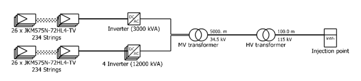
If you want to define a MV run of 5km, then simply define it as such in the Ohmic losses menu. The distances do not print, however, in 7.3.4.

-
There is a glitch in the single line where if the user zooms in on the single-line, the distance labels disappear for the MV and HV runs. To get it back, one must toggle the main labels button. The distances also disappear when printing.
-
My guess is that you have defined an HV transformer under detailed losses, and so it is showing up in the single line. Remove the HV transformer, and it will show only the MV transformers to the injection point.
-
Have you defined a frame size?
-
unused energy (grid throttling) equal to 0%
dtarin replied to Wanderson Alves's topic in Problems / Bugs
You define the ac losses. Enter them according to your design. -
unused energy (grid throttling) equal to 0%
dtarin replied to Wanderson Alves's topic in Problems / Bugs
Your AC losses are probably too high. Is 3.2% accurate? I dont think I've ever seen a plant with AC losses that high. -
I'd like to re-suggest the ability to define a monthly soiling profile in batch simulations. This will facilitate running time-series analysis for soiling losses.
-
Not from what I've seen.
-
Yes, or the crosshairs.
-
Thank you.
-
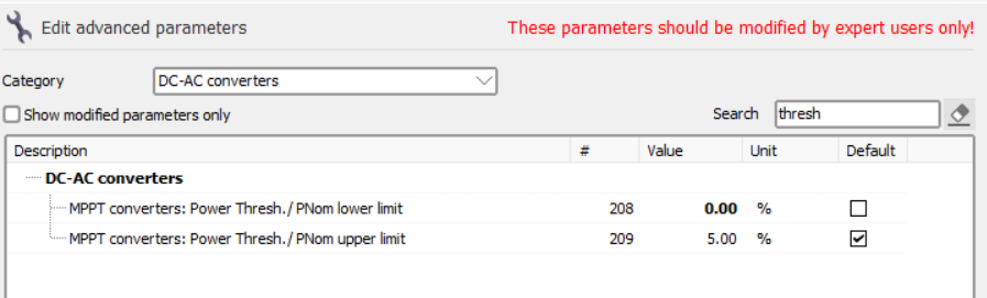
Threshold loss when array power > inverter threshold
dtarin replied to smeredith's topic in Simulations
In general, it looks as though PVsyst has a minimum built in, irrespective of what is stated in the OND file. EArrayMPP must be greater than 0.5% of Pnom, and I think there might also be an irradiance requirement, although I can't find the details at the moment. Changing the setting below did not change behavior in my test. Results were pretty consistent with the 0.5% requirement, but there were four hours where there was inverter output below this.
-
-
Change the tilt to -90 or 90 after it has been created and placed into shade scene.