C. Amorevole
-
Posts
11 -
Joined
-
Last visited
-
Hello everyone, I need your help with a scenary export problem: In order to evaluate the producibility of a PV plant, I usually work with PVCase to discover how much peak Power I can install on the studied area. This software enables me to export in different formats and I can use it to work on PVSyst. My question is the following: can I export in a .dwg format the 3D scenary on which I am working on PVSyst? In addition to this, I need to know also: can I export a plant scenary in which all the trackers are inclinated on an axis phi different from zero? thank you in advance for the answer
-
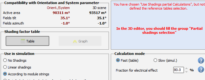
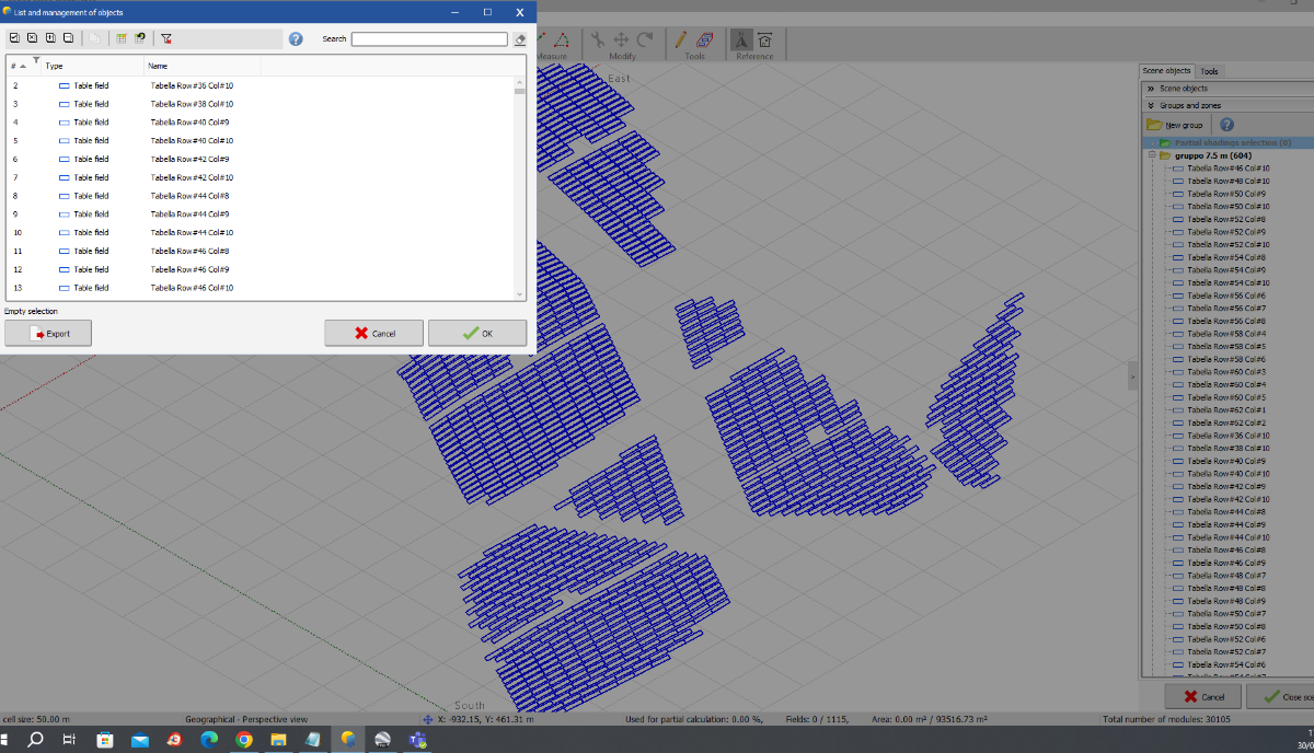
I am working at a fixed PV plant characterised by an irregular terrain slope and bifacial modules. In order to choose the exact projects settings for the plant, I decided to divide the terrain slopes into 2 main categories and define the correct pitch for each of them: eventually I obtained 2 areas with same projects setting in each of them (same pitch, same tilt, ecc). Importing the plant in the 3d scenary I faced this screen: this is the first problem: I tried to fill the group "partial shadings selection" but I couldn't select exactly the structures I need, unless selecting one by one in the "list and management of objects" in the "partial shadings group" in 3d scenary: I tried to avoid the problem, modifying the hidden parameters and enlarging the "pitch rms limit" from 0,1 to 1 meter. I would understand if this adjustment may influence only in near shadings 3d calculation (and this means that I would correctly evaluate the shadings losses) or it may affects also on the simulation. Reading the orientation settings, it seems that it considers only one orientation (fixed tilted palne). It may be quite a big approximation. Do you know a different/better solution?

-
Hello PVSyst forum!! I need your help. In the ohmic losses definitions I had an issue to input some characteristics of my implants on PVSyst. I am talking about an utility scale project: my PV system is characterized by an in-out system cabling for the subarrays: the wires go out from a power station (structure in which there are many electro-mechanic instruments such as inverters, combiner box, transformers, ecc) of a subarray and go in a new power station of a different subarray, obviously the new cables that go out from the new power station wil have a larger section. This helps to use less cables length, saving money. I wonder if this configuration may be implemented in PVSyst. Can anyone help me solving this issue?
-
In byfacial system definition I need to project a bifacial model for my fixed structure installation: I know that it could be an unusual idea, but I need to compare my FV tracker implant to a FV fixed implant with same characteristics (same module, byfacial model, ecc). I need to do this in order to verify the improvement of a new and innovative PV system respect to a standard PV project (respecting the guidelines of the italian ministry of the ecological transition). I noticed that a bifacial model is not compatible with the fixed planes in PVsyst. Is that true or can someone explain me a way to input this feature? Thank you for the help
-
Carbon Balance: detailed system LCE
C. Amorevole replied to C. Amorevole's topic in Shadings and tracking
P.S. when I asked how may I modify this parameter I obviously meant how I may discover the default weight value associated with the tracker -
Hello PVSyst forum, I was trying to evaluate the saved CO2 emissions for my PV implant project. While I was entering the values of all the listed voices (PV modules, BoS, Additional, ect), I had some issues into the evaluation of the supports/trackers' weight in BoS category: since the software (correctly) plans to install 2892 trackers, the project variance gives the value of 3759600 kg; I don't think that this weight is a correct value and I would like to change it, or anyway I would like to know where I may modify this value, since there is no evidence in settings parameters. Can anyone help me in this issue? thank you in advance C.A.
-
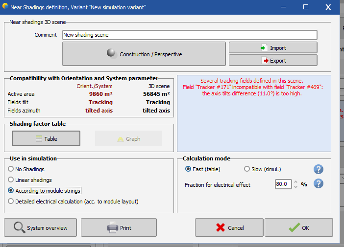
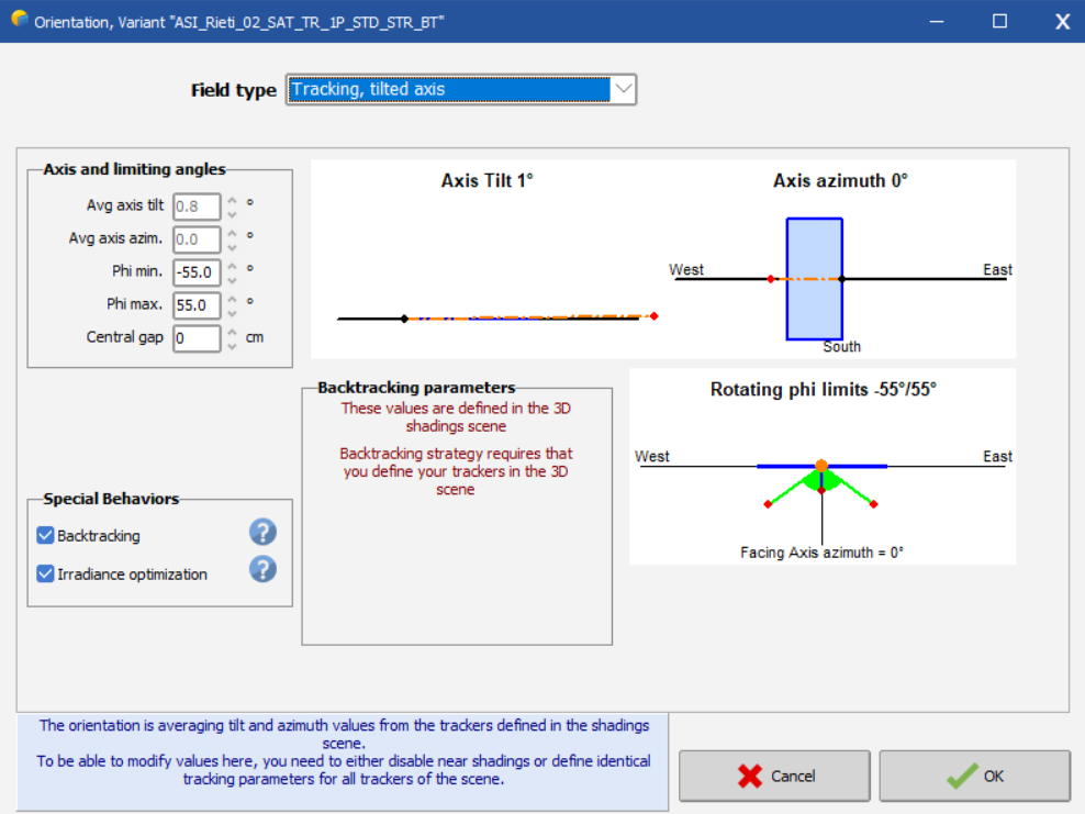
Hi PVsyst, I wish you help me solving the following problem: operating on the 3D scene there is the following screen: I thought to solve the problem working on the "Orientation management" in the 3D scene, but it is an option deactivated: Where may I operate in order to correct this issue? Thank you in advance for the help
-
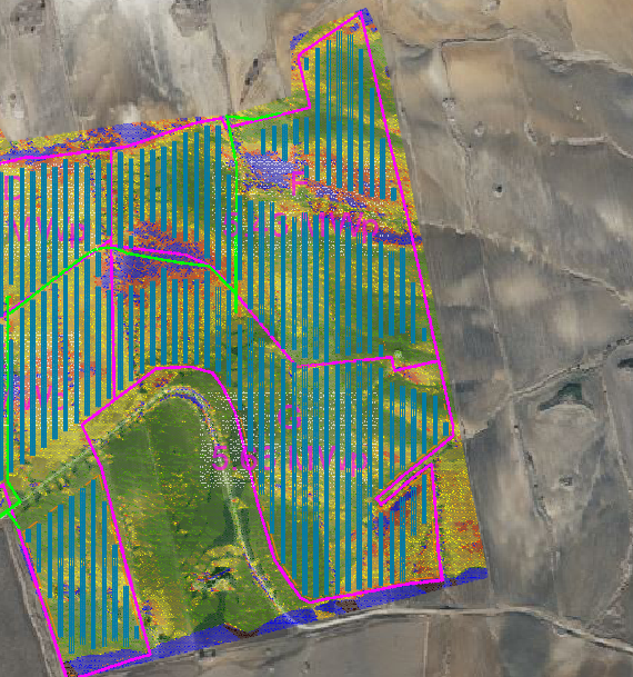
Hi everyone, I am trying to import a .csv file in 3d scenario but something does not work correctly. Even if it is a procedure that I often use, this time I don't understand why it does not import correctly the terrain mesh. As you may look in the following picture, the terrain mesh imported does not match with the panels configuration. The implant seems to be moved from the terrain. The original configuration terrain-implant should be something similar to what the next image describes. In other words the terrain mesh (.csv file with different color for the different slopes and inclination of the terrain) occupies almost the same area of the pv implants (it is just a little bigger): Is there something wrong in the import procedure that I use??? Is there a setting option that I should manage in order to correctly complete this import phase? thank you in advance
-
Hello PVsyst forum, After readings the suggestion (the "?" icon) where it talks about the little tables systems, I had a question about the partition's effects: Generally (since I use string composed by 30 panels and my trackers are composed by 30 panels too or 15), according to what suggestions in the image above suggest, it seemed convenient to me to place the little tables close to each other. So "all the bottoms will be shaded at the same time, and the rest of the table will become inactive, in the same way as for a big table". What does this last sentence mean? To become inactive means that there is no contribution on energy production by the totally or partially shaded tables/strings? what does PVSyst calculate on the string if only part of it (for instance only a single table of 15 modules of the 2 (2x15=30 modules=1 string) that combine the string) is shaded and the rest is totally radiated? Does it involve also the fraction for the electrical effect? If yes, how does it work? thank you
-
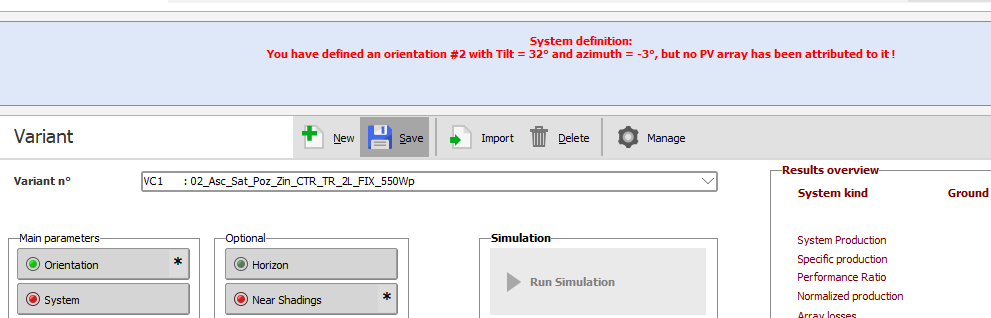
Hello PVsyst forum, I had a problem in my project about the topic "the area od the 3D fields is lower than the area of the modules defined in the subarrays". I'm working to a fixed PV project with no particular limits on the slope tolerances. So it means that the fixed structures (with an inclination of the module of 32°) have the same slope of the terrain. The programme shows what follows: the problem seems to be solvable connecting the different orientations (defined in the "orientation" parameters) with the right sub-arrays defined in the "system" parameters. My question is the following: since I can't define a single orientation for each different string or structure in the "orientation" parameters but only for the sub-arrays (group of strings), I can't be very accurate into the assignment of the right orientation in "system" parameters. Anyway I don't recognise a correct way to associate the right orientation to each subarray. Can you help me solving this issue? I should find a valid average orientation for the sub-arrays (probably in "orientation" parameters) and assign it in the "system" parameters. Is it correct? can you explain me how it can be done? it doesn't seem to me to be very easy to do. thank you for the help.
-
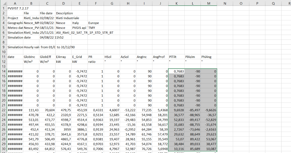
Hello everyone, I need an help to solve some issues on my project's results. I am working at a PV system with the following characteristics: - trackers with monoaxial system rotating on the N-S axis; - fixed tilt; - fixed azimut; - adapted to the terrain configuration. Looking at the advanced simulation results, I noticed some strange values under the ''Pltilt'' and ''PlAzim'' voices. I attach some pictures to explain my issue. As soon as I looked at these results, expecially at the PlAzim and PlTilt values, I immediately asked myself: - If my trackers have to rotate on N-S axis only, why do PlTilt and PhAzim values change? - where can I found on PVsyst a formula on which is explained how these values are evaluated (if I can find it)? - Is it correct to define the PlTilt as the inclination of the tracker respect to the horizontal axis? If yes, it has to be fixed in my configuration, isn't it? - Is it correct to define the PlAzim as the inclination of the tracker respect to the Azimut? If yes, it has to be fixed in my configuration, isn't it? thank you for answering.