-
Posts
889 -
Joined
-
Last visited
Everything posted by dtarin
-
Use batch simulation. You can define simple parameters like GCR, number of strings, etc. You may want to consider a simple variant (unlimited sheds, etc) to get faster run time or ability to change pitch if you are interested in that. Batch simulation is where you create one variant, define in a csv file the simulation parameters for each simulation, 1 per row. PVsyst will step through each one and simulate one at a time and output the 8760 data for the variables you have selected.
-
import reference images from the source you are importing from. CAD layouts, google, etc. use reference image to line up the objects. I would first move the image to match the PV and wind turbines, then move the terrain, just easier to select one object vs many
-
Yes, in the shade scene, you can pull up all objects and export all data. It is under tools menu.
-
See thread here.
-
EArray = EarrMPP - (IL_Pmax + EGridLm) Clipping losses.
-

The 3D model (.3ds) file size is too big to import and work
dtarin replied to Manasa's topic in Problems / Bugs
separate array into separate areas, import one at a time, save the objects on each import within PVsyst once saved, then open them all up in single shade scene. if the file is that big consider if you are importing trivial things. if there are significant trees, consider deleting them and adding the trees from within -
Yes, as long as string size is the same and the input currents are within inverter spec, you can do anything. But the question is not that, but instead if mppt inputs can be jumpered. With chint inverters, they can, at least for the 50 and 60kw versions. Haven't used string inverters in a while. We ran into a situation where they weren't jumpered in the field and we were getting high losses/overloading. After they were jumpered, we saw expected performance. havent used Huawei so don't have anything to help you with them specifically at the moment.
-
It is not used for production (yield).
-
Which manufacturer said this? You may not want to power share if it cant be done in the field, otherwise you will underestimate your clipping losses. Take for example you have a DC/AC ratio on one MPPT input of 1.0 and on another MPPT input a ratio of 1.4. The latter will have high clipping losses if you don't have power sharing in field. If the DC/AC ratios are similar or the same, then I think you could be fine, but if they are significantly different, I would not.
-
You have a very low DC/AC ratio for that inverter. To get around this, go into advanced settings and set the following. If you need to adjust it lower, set the first one there to .01. The inverter is oversized for that design though, so you might be better off with something smaller.
-
Maybe a bug or glitch. Set it to horizontal N-S tracker in orientation menu, save the variant, close and reopen PVsyst.
-
Under field type select horizontal N-S tracker, not the one you have selected.
-
Correct, they are illustrative only for the chart, and serve no function in calculation.
-
There is no single right answer. Consider April, snow loss not very substantial, the average is 0.12%, which means half the time it will be less and you would consider that to mean there is not a "cleaning event" taking place. The preceding month is 0.76%, which is also low. It would be more helpful to look at the rainfall and snowfall quantities in inches instead of the soiling percentages to get an idea of how much precipitation (soling/liquid) it is receiving on average. And then keep in mind these are averages. Do you want to be conservative or aggressive? You can consider a number of ways to come up with a combined profile. I dont have all of the data, but just based off this might consider adding a baseline soiling rate to Jan, Feb, Mar, and Dec snow loss %s, and take the soiling loss %s the remainder months.
-
2727/96 = 28.4 mod in series. Your design specs are off. What is the correct minimum site temperature? You're carrying the PVsyst default of -10degC. Separately, it is a difference of one module, or .036%, not very significant. Depending on the site temperature and the correct string size for this location based on the module selected, you may exceed the maximum input voltage of the inverter by increasing the string size, but to the previous point, the impact is not very significant in that regard either.
-
It depends on the type and size of plant. A rooftop installation will probably have higher degradation than a large utility scale plant that has on-site operators and regular O&M support. In the absence of operational data, use the module datasheet for the Average Degradation Factor. If you want to consider system degradation, increase this figure above the module warranty value. There are some studies out there on I/V mismatch but published research is limited/lacking. If you don't have any guidance there, focus on aligning the avg. degradation factor according to expectations.
-
Model these as separate variants when using bifacial modules, combine post-pvsyst.
-
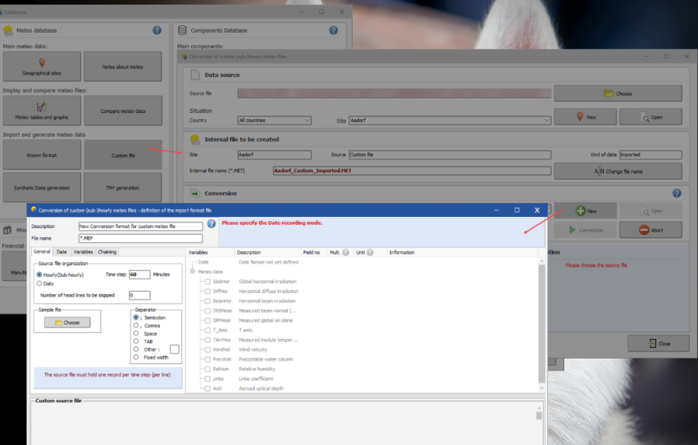
It could be something with your file type and delimiter settings? Ensure that hasnt changed. Aside from that possibility, your measurements are not correct. GHI should not be 4,000 W/m^2. Temperature, albedo, and wind speed look okay, but the irradiance variables are not (GHI, DHI, DNI). You can try using the PVsyst standard template if reusing vaisala doesnt work, but I would suggest import using custom meteo. You will define the details and each column and variable that is being imported. More information can be found in the help and on the forums.
-

Confused tables when importing a PVC scene
dtarin replied to Nicolas T's topic in Shadings and tracking
I do not typically disable interpenetration for the reason Michele noted, and likely causing your increased shading loss. I would either increase the table spacing from within pvcase and reimport, if the tables are not numerous and it is a fairly large site, i'd just delete them, or manually adjust. Rather than going through the check one-by-one, try flying around the shade scene and identifying by eye. Since it is a fixed tilt system, you can also look in the areas where terrain is complex and causing the interpenetrations to reduce the one-by-one check time. -
The reason for the difference in electrical loss is because the string lengths are longer for the c-Si modules compared to the FS. After modifying the JKM partition as Michele noted, the elec. losses will come also come down for that module. I would evaluate how much shading is due to the trees compared to row-row to get an idea of whether or not you should include any electrical loss for the FS modules. Run a model with and without trees and compare the near-shading loss only (turn off electrical effect). Also run the shading animation in the shade scene throughout different times of the year to understand the shading patterns on the modules due to trees. If there is a lot of E-W shading from trees and there is a significant contribution, then including an electrical effect makes sense, and as michele noted, it should be low. Also, your jinko module should have an LID loss.
-
My only comment to PVsyst is that when PVGIS is used, the comment which displays the coordinates incorrectly shows the minutes ' and seconds " notations. The coordinates should read (degrees, minutes, seconds), but it is displays as such: 40°5"17', Long=-77°39"53', which shows degrees, seconds, minutes. Whether this is from PVGIS or PVsyst, I do not know.
-
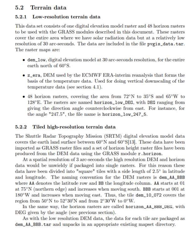
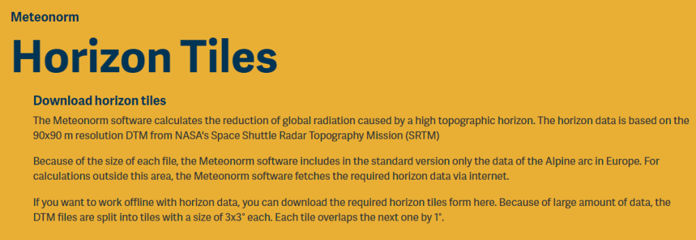
Meteonorm and PVGIS both use SRTM (depending on the coordinates); Meteonorm with 3 x 3 degree tiles, PVGIS with 2.5 x 2.5. PVGIS calculates to the first decimal while Meteonorm rounds to whole numbers. PVGIS uses 48 points (excluding 0 degree), 7.5 degree increments, whereas Meteonorm uses 1 degree increments. This causes the difference in smoothness. Repeated values are excluded in PVsyst. If you evaluate a complex site, you will find there is a significant difference in the number of horizon data points between the two. For example, one project site evaluated shows 29 points for PVGIS and 56 for Meteonorm. I would conclude that the differences lie with PVGIS and Meteonorm and the methods by which each is performing the calculations. PVsyst is importing the correct values one would retrieve directly from each source.


