
dtarin
-
Posts
897 -
Joined
-
Last visited
Everything posted by dtarin
-
Set dummy MPPTs in the OND file. You can set two for PCS 3 and 4, and create five sub-arrays in PVsyst for building 1, 2, 3, 4 and 5. You will then use the power sharing feature and set subarrays 1 and 2 (building 1 and 2) to PCS 3 using MPPT share and subarrays 4 and 5 (building 4 and 5) to PCS 4 using mppt share. Subarray 3 (building 3) I assume is 24 strings and you can put on two PCS in one subarray, no need for mppt share. There are other threads which go into detail on how to do this.
-
You would use 0.91 in PVsyst. If you run PF in PVsyst with 0.95 with a long MV run and a transformer, and you apply a grid limitation at the injection point, and set the grid limitation loss separate, you will still have an inverter operating at 0.95PF. Changing the length of the cable will not change this. You can confirm this by checking the maximum output power of the inverter. If you do not account for grid limitation loss separately, then the inverter output will be reduced further. PVsyst takes the grid limit loss and adds it to the Il_Pmax loss. For example, I have a 3.6MW inverter, I set a 0.95PF, with MV AC, XFMR loss, and a grid limit of 3.0MW applied at injection point but do not check account as a separate loss, my maximum inverter output (for this particular case) is 3034kW. When I check account as a separate loss, my inverter output is ~3420kW, or 0.95PF.
-
It will likely be resolved in the next patch. Downgrade to 7.2.17 in the mean time as this is unaffected by the issue.
-
You cannot batch simulate 3D scenes with terrain. If you have a standard block of trackers, you can vary that pitch, but they must be created from the tracker block and not be individual tables. It says there in the batch menu, "These parameters apply to regular arrays of sheds or trackers only!" To generate reports, check Create PDF Report in the batch menu under Simulation parameters.
-
Funny
-
Two ways. One, you can use a weather file which corresponds to each, or two, using a standard TMY weather file, calculate your P90 factor, and multiply your P50 8760 data with it to get a P90 dataset.
-
Reference letter for each building, does this mean that B, H, N, and P are different buildings, and hence, would be separate arrays? In any case, this is a pretty broad question without details, so I will give a range of answers. You can change the module wattage to fit your DC capacity better, round to the nearest string quantity that fits your DC target (as closely as possible), or use microinverters/optimizers. You may not be able to hit 79.58kW exactly, and will have to install something less that fits.
-
I agree, PVsyst only allows the last two variables in the table to be selected by the user, but all variables in this table should be able to be edited and selected by the user. If there is a way to edit all variables, I haven't found it yet.
-
50kW is your bin class size, not 200. Count the number of "steps", it is 20 steps to 1000, bin size of 50. The Y axis is MWh per each bin class of 50kW.
-
There are more hours in the year at one of the power output level compared to another. Filter your 8760 to verify.
-
@Michele Oliosi With 8760 data. I have not seen it elaborated on the forums prior.
-
EArrMPP = DC input into the inverter when max power point tracking EArray = EarrMPP - (IL_Pmax + EGridLm) It is the mppt DC energy minus the clipping losses, even clipping due to POI limit. POI clipping will also move the inverter operating point in reality, so I suppose that it why it is included? The help says the following, EOutInv = EArrMPP - InvLoss EGrid = EOutInv - (EACOhmL + EMVOhmL + EMVTrfL + .... + EGrdLim) This will change depending on if you have defined AC losses, whether you have accounted for unused energy from grid limit separately, etc. In looking at the equations above, we can see that it is indeed possible for EArray to sometimes be close to EGrid. If you have not implemented a grid limit and display as separate loss, you wont have EGrdLim (it will = 0). Regarding BESS, it depends on how your model is set up, so can't really say whether it is correct or not. This is DC coupled, correct? Are you sending EArray directly to grid (minus IL_Oper/Pmin/Vmin/Vmax/Imax) and IL_Pmax to batteries?
-
The software can only output hourly values.
-
Import the layout image and scale it, then draw zones on top of the image.

-
+1 Perhaps auto save changes into a running log that stores last N changes, in addition to a user-input comments/notes section.
-
It depends. What do your inverter losses look like? You don't necessarily have to change anything, but if you are getting high inverter losses , then maybe you want to reconsider the design.
-
I am running on two machines, laptop and desktop, and have not noticed a drop in performance.
-
I don't quite follow what this means. What is the minimum grid capacity and actual grid capacity? I can create a "connected to grid" simulation with a single module.
-
Have you tried the different filling schemes under auto distribution? You can also set strings manually. I think if you find something sufficiently close, it will be good enough. I am not familiar with sketchup, but looking at that scene there, you can probably do it in the 3D scene creator in PVsyst easily with zones, and then set as tables as you want. Also, if you do have a table, PVsyst in the module layout method there will still fill module by module, whether it is a table or individual module. I am not sure it will make a different with this shading method.
-
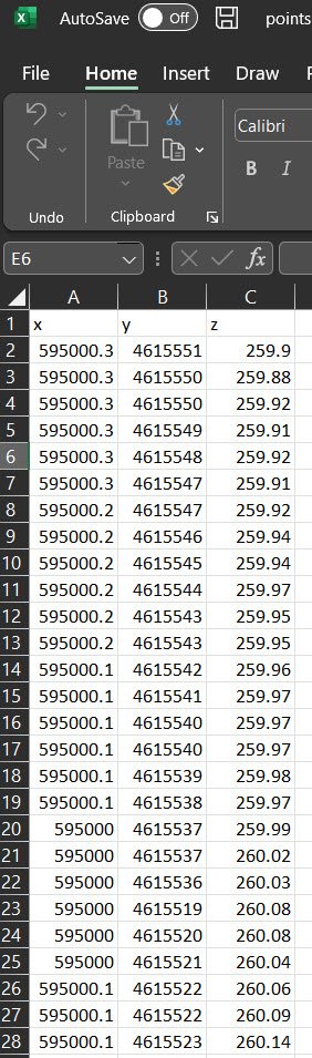
If you are importing ground data in x,y,z format, you need to have three columns with x,y,z data respectively, and one line as a row header OR no line header. It must be comma-separated in a .csv file. I would guess you have a different delimiter variable in your file and it has ignored all of the data.
-
 100 is a good default number. For a very large site, selecting higher is fine too, but it comes down to your system size. Shading losses most of the time are higher in the unlimited sheds model compared to a 3D scene (I have never seen it less but maybe in some cases it could be), so that is not unusual. Nb trackers is the number of rows. The unlimited sheds method excludes edge effects for the most part and assumes the rows are infinitely long.
 -
Unless someone here has already reached out to PVGIS and received an answer for this question, my guess would be no. Most (all?) satellite TMY data will not. Ground measured data can take horizon into account. PVGIS has a separate tool for determining horizon losses. They are pretty responsive (at least in my prior experience), give them a shout.
-
I see, yes, if perfectly flat, there will not be. In the image above, I thought your "LOT 1 - Flat" was the "flat" case you were considering. It looks like those modules are at different elevations (if even by a little), so there would be an electrical effect loss. There really are no completely flat sites, and ones that are very close will still have some electrical effect depending on the design.
-
How many of these locations where you need to fill are there? The answer can lead to two more questions: 1) What is the impact on the shading loss? Is it material? Have you captured shading losses sufficiently without filling these areas? If your site is very large (100s of MWs) and the number relatively low, it probably wont matter much. 2) If the number is low, a manual add would not be very time consuming. Create a block of individual trackers at the pitch, then copy/paste into the areas, and giving it an exact pitch spacing from the adjacent tracker. This doesn't answer your question on development queue, but more to provide an alternative perspective/work-around.
-
Also, simulate your "Flat" scenario according to strings. It looks like you have modeled it with linear shadings, so this isn't a good comparison.