-
Posts
890 -
Joined
-
Last visited
Everything posted by dtarin
-
When you multiply a random variable by a constant, the mean gets multiplied by the same constant and the variance gets multiplied by that constant squared. Xi are iid random variables.
-
For any single year that is the case. For multiple years, the uncertainty due to annual variability decreases, so this parameter needs to be separated out and used with the equation in my previous post, and then added to the other uncertainty quantities in full. My example was not quite correct in this regard.
-
If your trackers have any N-S tilt it will show tilted axis for the 3D scene. Horizontal axis is orientation type in Pvsyst. You would not want to change it to horiz. axis if your scene is 3D and you want to account for slopes in your tracker tables. Run (or re-run) the shading table, and it should update to tilted axis for Orient/System. You may need to go back into the orientation menu (to make sure it updates there and the tilt updates if it is non-zero average tilt) after generating the shading table , saving it, and exiting the shading menu for it to then update in the orientation menu.
-

Effective Energy at output of array doesn't match sum of losses
dtarin replied to nico7904's topic in Simulations
I calculated 1,253,579,619.69, which is a difference of 0.047%, possibly because your waterfall is only showing the first decimal. It can be displayed to third decimal. 1436079647 1431771408 -0.30% 1315797924 -8.10% 1315797924 0% 1322376914 0.50% 1309153144 -1% 1280351775 -2.20% 1272669665 -0.60% Total 1253579620 -1.50% PVsyst 1254163298 0.047% -
For a single year, σ = 3.11. For two consecutive years, σ = σ / √2 Var( X̄ ) = ( 1/n )^2 * Var( X₁ + X₂ + ... + Xₙ ) = ( 1/n )^2 * ( nσ² ) = σ² / n
-

What parameter in 8760 to reference to identify near shading?
dtarin replied to Lucy's topic in Meteo data
ShdLoss is the total near shading loss, which includes beam, circumsolar, diffuse and albedo components. FShdGl is the global shading loss factor, so 1- FShdGl will give the percentage value. If you wish to calculate from irradiance values, it is (GlobShd/GlobHrz - 1). If your model does not have horizon loss, GlobInc is the denominator. If you want to identify direct (beam) shading (i.e., from a tree or module), you would use ShdBLss or FShdBm; FShdBm is typical. How to use it depends on your application. For example in capacity testing, it is often suggested to use below 1.0; however, this may not be the best option depending on your plant, which month(s) the test is occurring, etc. -

PVCase Terrain Following Tracker Underestimating Losses
dtarin replied to Daksha B's topic in Shadings and tracking
PVcase advises to run two simulations. https://help.pvcase.com/en/articles/8559799-modeling-terrain-following-trackers-from-pvcase-in-pvsyst -
Your panels are placed with a 25 degree tilt and 0 azimuth onto a sloped terrain, resulting in an effective tilt and azimuth used in the simulation for calculations. This is typical.
-
If you are not running specific PV software, such as AutoCAD plugin PVcase or something similar that can easily export from CAD, one way is to export the surface as a collection of points (X,Y,Z) in meters as a CSV file. They will need a screenshot from CAD of the surface and general site boundaries to align the modules within the parcel boundaries. In AutoCAD, the surface topographical lines can be exploded and exported as points easily, using the start or end points from the exploded lines which (in my experience) reduce down to a line segment with three points.
-
It selects the lowest pitch automatically to avoid shadings. You can select any rack you want to change it or manually enter it in. Calculate a weighted average based on the number of tables at each pitch if they are different.
-
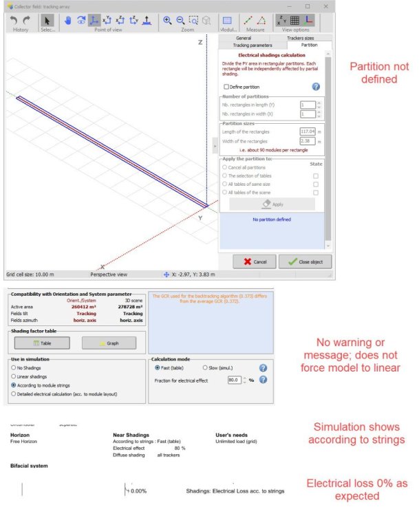
As noted in title, PVsyst allows the user to run a simulation with according to strings selected and an electrical effect defined, but without having defined a partition in the shade scene. In prior versions I recall this creating an error or warning, and/or forcing the simulation back to linear when a partition was not defined. The reason this is occurring is because as you can see in the screenshot, a higher GCR is selected and the site is practically flat; when this GCR is used for the backtracking algorithm, electrical loss is apparently 0% from shading due to adjacent tables. If I select a lower GCR to be used for backtracking, the simulation then forces the error and directs the user to define a partition. However, this should not be the case. If according to strings is selected, it should always force the user to define a partition, even if there is some internal check to see if there is shading from adjacent sheds (that's how it looks to me anyhow). There are trees in the shade scene, so even if there is no shading due to tables, there should still be electrical effect loss, which is why according to strings should force the definition of a partition.
-

Different global incident in coll. plane with the same meteo data
dtarin replied to Mkitay123's topic in Meteo data
Your GCR has increased in the new simulation, which will result in a lower transposition factor. In the shading scene under backtracking management, the pitch used for POA calculation and backtracking is selected, either automatically or specifically by user. POA (GlobInc) doesnt not consider shading losses, GlobEff does. -
It may depend on where these tables are in the array and the site conditions. For an exterior table that has significant tree shading (or other object shading), strung in U may be better (2x2). For interior tables, where most of the shading will be from the rows in front, stringing across the entire table (and not in U) is likely better (4x1).
-

Error: Area error with 3D ground modeling
dtarin replied to JoaoReis's topic in Shadings and tracking
- 4 replies
-
- ground
- orientation
-
(and 1 more)
Tagged with:
-
-

Batch simulation - Not getting .csv 8760 for each SIM
dtarin replied to JStief's topic in Problems / Bugs
Phi is the variable to change for this exercise. Phi_min = Phi_max in the batch parameter file to simulate a tracker at angle. Tilt and azimuth should not be changed. -
If your site is that large (GWs I assume here), you're better off running them in separate variants. Also with a site that large, you may not need to model the entirety in the first place, as long as you have a scene that is representative of the overall site.
-
It does not, trees are solid, static objects.
-
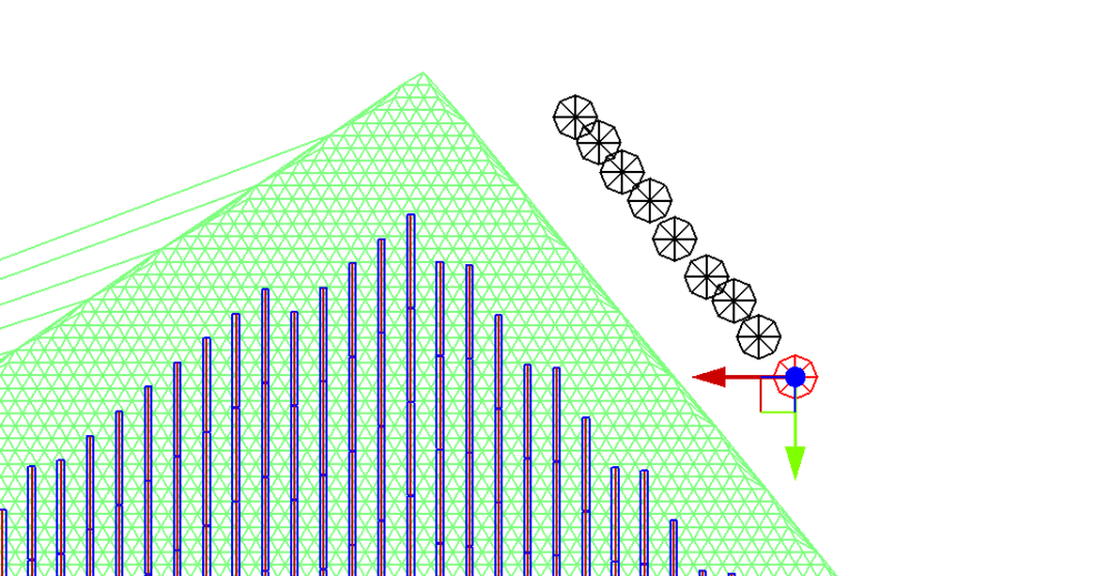
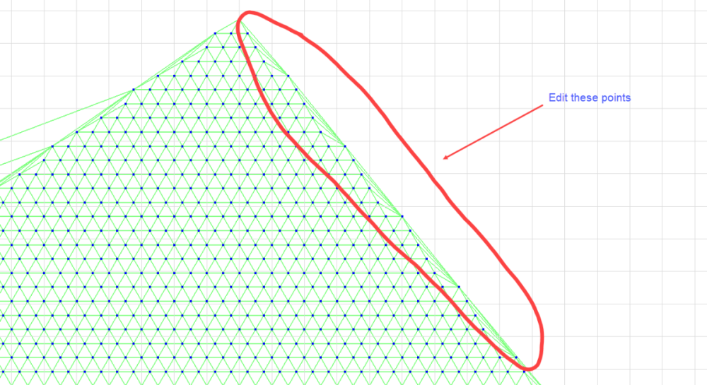
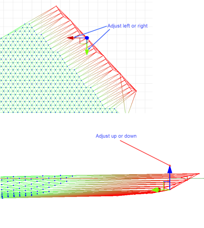
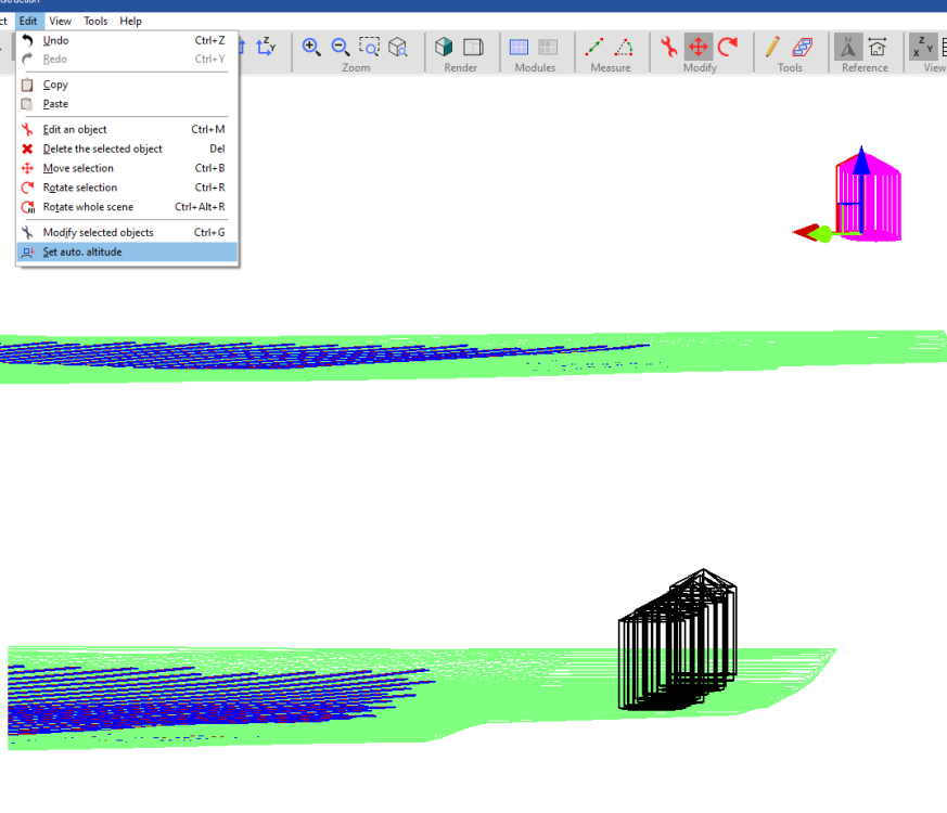
If your trees are over the terrain, you can place them onto the terrain with any offset desired using edit > set auto altitude. If your terrain surface is limited, and you need to add trees that are outside the boundary, then you can manually adjust the edges of your terrain by moving points individually in the X, Y, or Z direction (you can select multiple at once, it is not restricted to a single point, in case previous statement was misleading). After the terrain surface is adjusted, use auto altitude on all objects.
-

Batch simulation - Not getting .csv 8760 for each SIM
dtarin replied to JStief's topic in Problems / Bugs
-

Aligning PV Plant and Ground Topography
dtarin replied to symbiosis's topic in Shadings and tracking
You need an image of the modules on terrain, and then import and scale the image into pvsyst. You can then visually align the modules imported from CAD and the ground topography from Sketchup to the imported image.

