-
Posts
889 -
Joined
-
Last visited
Everything posted by dtarin
-
After having a second look (and since I can't edit), use power sharing for sub arrays 2-5 and balance the DC/AC ratio across all inputs.
-
The DC/AC ratio is very high, to the point that the inverter manufacturer may not warrant the product in a PV-only system. The maximum DC/AC ratio according to the datasheet is around 150%, or 1.5, which is fairly common. Is this a DC-coupled battery system?
-
My comment for #1 is that 0.02% is in the noise. I don't much for #2, but you can always rename them in windows explorer without having to rename one at a time in PVsyst.
-
Backtracking angles (Phi) and Tilt are two different things. The list you have there is showing tilt in the N-S direction, and this is a static number that doesnt change. The tracking method and phi angle range are set under orientation menu. PVsyst does not allow for custom backtracking angles, only what is included in the software. T
-
You can change your timestamps and import "10 hours" of data, and then change the timestamps after simulation to minutes.
-
Increase tolerance to 20 degrees, press identify.
-
The central gap in PVsyst is for 2P trackers, and defines the spacing between the two modules in portrait. It does not define gaps for motors or bearings .
-
Modify the ond file and reduce the number of mppt inputs. Save this as new file.
-
Screenshot looks correct…
-
Yes, for wind speed as well.
-
It is the average temperature for the entire month using hourly data. You can export the data to csv and confirm under Advanced Simulation.
-
You can export all of the necessary variables to determine what you have requested under Advanced Simulation. Select the required variables, and the software will export the data to a .CSV file. From there you can calculate what you need on a monthly basis. I dont know what peak capacity or export capacity mean, perhaps max instantaneous output power? A standard TMY weather file is a P50 simulation. Unless you have specifically a P90 weather file, you will need to calculate P90 from the P50 yourself.
-
https://www.pvsyst.com/download-pvsyst/
-
To my knowledge, PVsyst cannot run a meteo file which is longer than a year. So regardless of how you approach, it will split them up or you will manually. Convert the format of your CSV into the PVsyst standard you linked. Here is screenshot of what I did, it worked fine and created 23 MET files. You may need to adjust the hour shift or time shift (in minutes) depending on your location.
-
It can import monthly data, it does not have to be a full year, and it will create hourly average. Screenshot below for a single month of 1-minute imported data.
-
You can import 15 minute data and pvsyst will convert to hourly
-
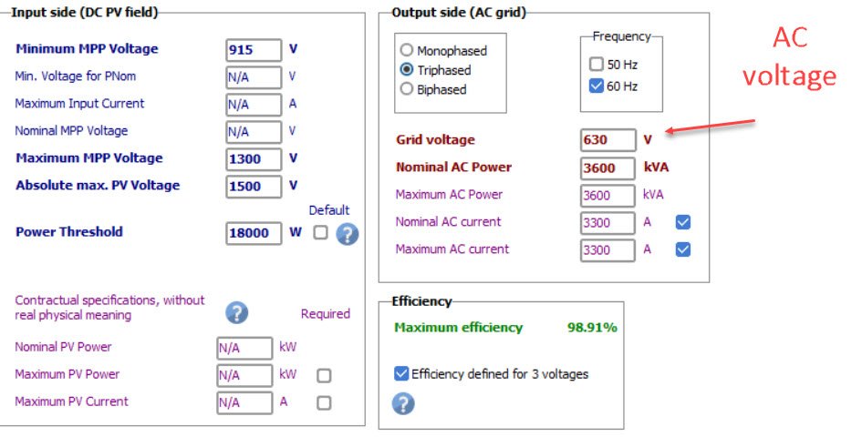
You wont be able to find DC voltage in the OND file, it comes from your PV system and is dependent on other factors. You will need DC voltage from the 8760 data. AC voltage is stated in the OND file.
-

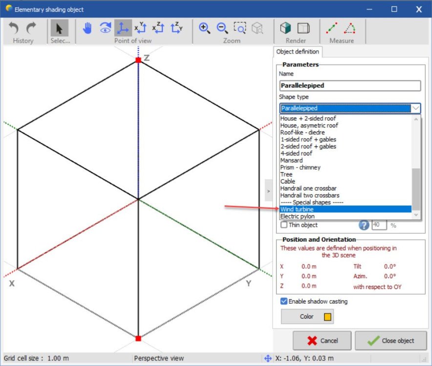
How to import obstacles into the 3D module layout.
dtarin replied to sujinlee's topic in Shadings and tracking
Go to create > elementary shading object. Wind turbines are available, as are other objects. If you need something specific, you can either build it piece by piece or use an approximate shape. -
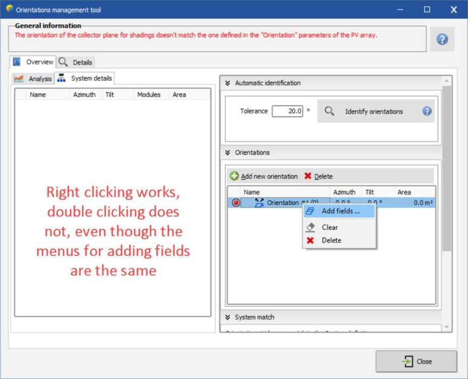
I did find a bug, though, @Michele Oliosi. If I delete the orientation, select add new, I get an empty orientation. Double click, add fields, select all tables, and whether I click close or switch back over to the overview tab, the modules do no allocate to then new orientation, it stays at 0/0/0. It seems the only way to add tables to the orientation is to use the identify orientations button (doesnt allow custom allocation), or by right clicking on the empty orientation.
-
your screenshot shows 0 tilt, 0 azimuth, and 0module area. i am assuming there is an issue with your pvc import, or you dont have any modules assigned from within the shade scene. go in and allocate tables to that orientation if possible. module image for reference


