-
Posts
888 -
Joined
-
Last visited
Everything posted by dtarin
-
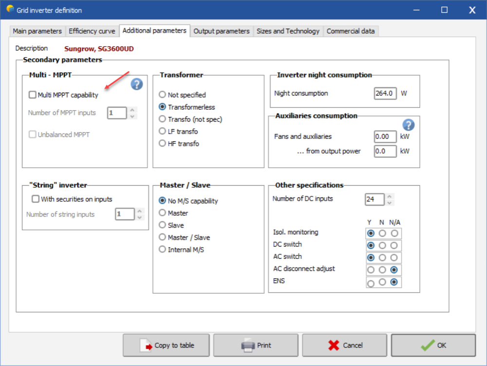
add dummy mppt to OND file, share the inputs in one of the inverters between two arrays with two different panel types. you will not have one module type per inverter.
-
Maybe this can help
-
One additional request for the carbon emissions report, the units for energy don't change with the report options setting for units, would be great to have it change there also.
-
It would be great if in the carbon balance menu (or the entire Economic Evaluation tool), EGrid wasn't fixed to the project and instead could be entered by the user. We don't always have complete losses in PVsyst and often post-process for additional losses and considerations, but could still make use of the economic evaluation and/or carbon balance tool if we could enter Egrid.
-
Search "Batch mode - Parametric studies" in the help menu.
-

How to download the month wise expected module temperature in deg c
dtarin replied to winothkanna's topic in How-to
Module temperature can be calculated, there are formulas online you can search. In PVsyst, there is an output variable called Tarray, in some places of the help it says cell temperature, and others, it says module temperature. It would be great to get some clarification here @Michele Oliosi. -
Yes, there is a section where the trackers are listed, then below, the objects, then in a new section where zones and groups appear. Create a group then add trackers to it. Select the trackers then I think you right click the group and add to it.
-
For why PVsyst shows 80 modules instead of 81, check the module spacing you have in whatever software is generating the PVC file, and what you have by default in PVsyst. If for example you are using PVCase with a module spacing of .01m and your PVsyst default is .02m, you will not get the same number of modules. This does not really matter though. PVsyst is calculating shading losses here, nothing else, so if the area of the tracker block in total is representative, then I dont think it matters if it says 80 or 81. The generation calculations are done based on the system definition, not by the module quantity in the shading scene. Try setting PVsyst default module spacing to 0.00 (X and Y), then reimport the PVC file.
-
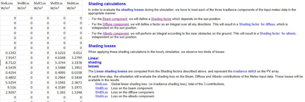
Near shadings consists of beam, diffuse, circumsolar, and albedo losses. @PVsyst, circumsolar is missing from the help menu, see attached.
-
It is indeed an OR function. You can apply your grid limit as defined in the menu at the inverter or the injection point after AC losses, but not both. To do both, export the 8760 and set different limits in excel: 1st at the inverter, then apply AC losses, then apply POI grid limit.
-
Diffuse shading
-
You have to use all mppt inputs.
-
Your inverter already has enough mppts, sorry I assumed you were modeling with something that didn't
-
Set dummy MPPTs in the OND file. You can set two for PCS 3 and 4, and create five sub-arrays in PVsyst for building 1, 2, 3, 4 and 5. You will then use the power sharing feature and set subarrays 1 and 2 (building 1 and 2) to PCS 3 using MPPT share and subarrays 4 and 5 (building 4 and 5) to PCS 4 using mppt share. Subarray 3 (building 3) I assume is 24 strings and you can put on two PCS in one subarray, no need for mppt share. There are other threads which go into detail on how to do this.
-
You would use 0.91 in PVsyst. If you run PF in PVsyst with 0.95 with a long MV run and a transformer, and you apply a grid limitation at the injection point, and set the grid limitation loss separate, you will still have an inverter operating at 0.95PF. Changing the length of the cable will not change this. You can confirm this by checking the maximum output power of the inverter. If you do not account for grid limitation loss separately, then the inverter output will be reduced further. PVsyst takes the grid limit loss and adds it to the Il_Pmax loss. For example, I have a 3.6MW inverter, I set a 0.95PF, with MV AC, XFMR loss, and a grid limit of 3.0MW applied at injection point but do not check account as a separate loss, my maximum inverter output (for this particular case) is 3034kW. When I check account as a separate loss, my inverter output is ~3420kW, or 0.95PF.
-
It will likely be resolved in the next patch. Downgrade to 7.2.17 in the mean time as this is unaffected by the issue.
-
You cannot batch simulate 3D scenes with terrain. If you have a standard block of trackers, you can vary that pitch, but they must be created from the tracker block and not be individual tables. It says there in the batch menu, "These parameters apply to regular arrays of sheds or trackers only!" To generate reports, check Create PDF Report in the batch menu under Simulation parameters.
-
Two ways. One, you can use a weather file which corresponds to each, or two, using a standard TMY weather file, calculate your P90 factor, and multiply your P50 8760 data with it to get a P90 dataset.
-
Reference letter for each building, does this mean that B, H, N, and P are different buildings, and hence, would be separate arrays? In any case, this is a pretty broad question without details, so I will give a range of answers. You can change the module wattage to fit your DC capacity better, round to the nearest string quantity that fits your DC target (as closely as possible), or use microinverters/optimizers. You may not be able to hit 79.58kW exactly, and will have to install something less that fits.
-
I agree, PVsyst only allows the last two variables in the table to be selected by the user, but all variables in this table should be able to be edited and selected by the user. If there is a way to edit all variables, I haven't found it yet.
-
50kW is your bin class size, not 200. Count the number of "steps", it is 20 steps to 1000, bin size of 50. The Y axis is MWh per each bin class of 50kW.


