
dtarin
-
Posts
897 -
Joined
-
Last visited
Everything posted by dtarin
-
For clarification I am not suggesting LID divides by 2. LID occurs on shorter timescale compared to annual degradation and should be taken in full. My overall comment is that taking 1st year degradation from the datasheet and subtracting (annual degradation/2) to get LID may be conservative and something to keep in mind. Different modules may test higher or lower in LID and it is recommended to have module-specific data to support LID assumptions.
-
Lid and annual power degradation are separate degradation modes. They also occur on different timescales. It is common to assume first year annual degradation divided by 2 (as is done in PVsyst). This may be conservative, which could be fine, but may not be ideal in other aspects. For example, most PERC modules are Ga-doped and certain suppliers test quite low on LID (~1%). For most PERC modules, first year degradation is 2%, 0.45% annual degradation thereafter. The method above would add 0.775% loss over what would be expected for the first year. For TOPCon modules if your LID is 0.5%, you'd have an additional 0.3% loss in year 1. Might be fine in some cases but not in others, something to keep in mind.
-
 Night losses are everything the plant draws at night, including transformers. The utility does not distinguish between devices. Most utility-scale plants (in my opinion) do not have nighttime disconnects on the MV equipment. The MPT is always connected to the grid. It is best to assume (unless you have a detailed design stating otherwise) that the plant will not be disconnected from the grid at night. The caveat here is that depending on how you are using your energy model and if it is flowing into a financial model, you may want to separate these out in case they are considered independently in the financial model.
 -
Transformer losses will come from the manufacturer. If you are modeling transformers in PVsyst, ensure the no-load losses are captured there, and it will reflect in the 8760 for night hours. For MV transformers, 0.10% - 0.16% is a good range for no load losses, for MPTs, 0.04% - 0.06% is a good range. Other items you will need to determine based on plant equipment. 0.2% of POI rating for total hourly night loss at the revenue meter is a good estimate overall (utility scale SAT). Use something higher for cold-weather plants.
-
PVsyst does not show Plane of Array Irradiance AFTER backtracking
dtarin replied to Ahmad's topic in Problems / Bugs
If backtracking is enabled, GlobInc considers backtracking, as does GlobEff, and all other irradiance parameters. -
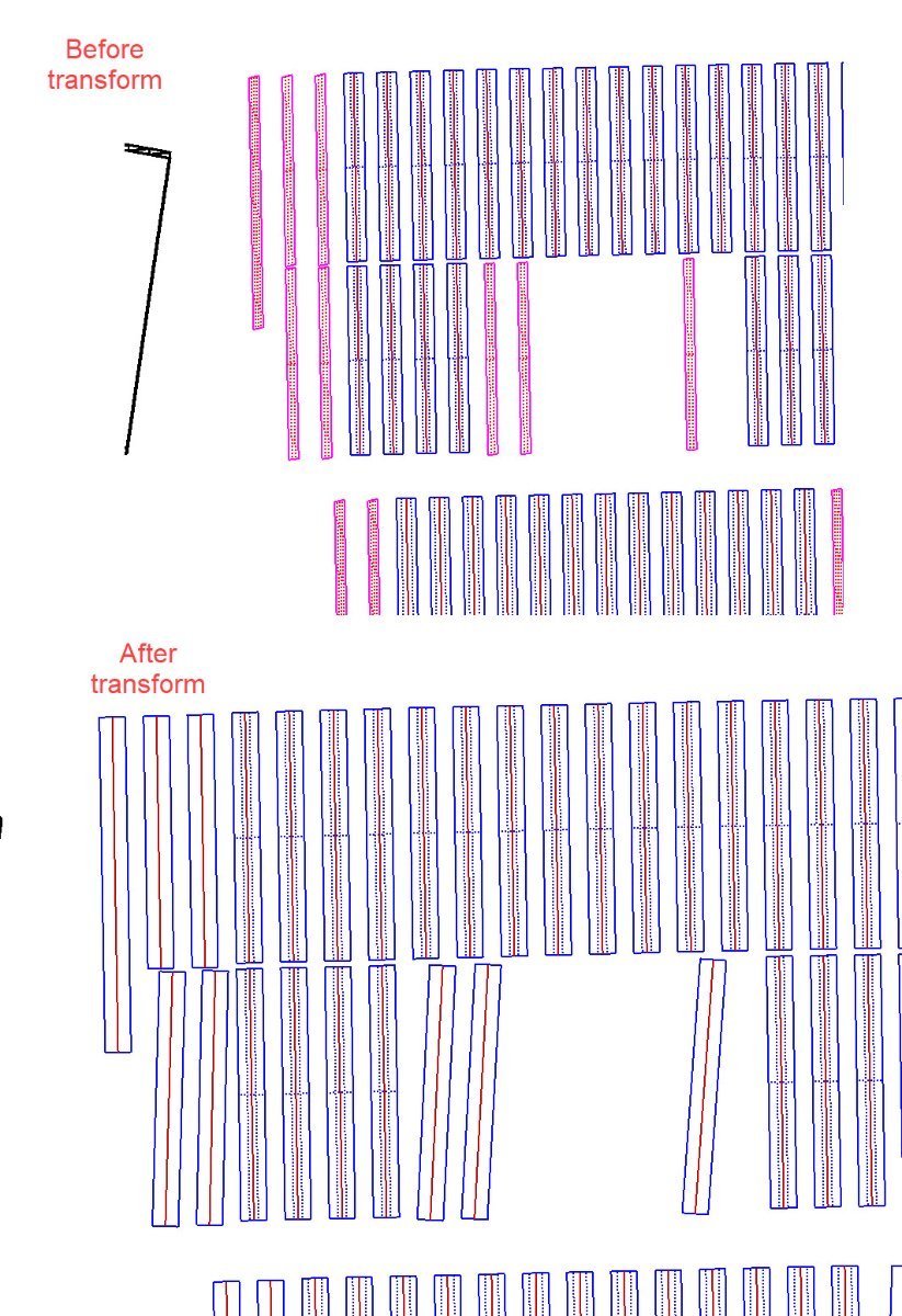
Transforming fixed tilt tables to trackers changes their orientation. It looks like the parameters are being passed directly to the new tracker object like azimuth and tilt, when these are calculated/defined differently for each type of object, and should be recalculated so that the object remains in place.

-
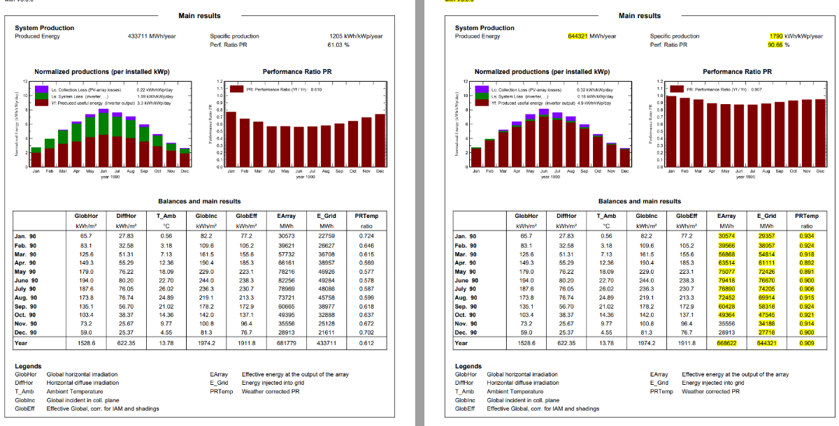
v8.0.6
-
The first module is not "inferior", module efficiency is 20% vs 17%, making it the better module. There must also be a significant difference in the temperature coefficient.
-
Custom tracker is a better option than central. It reduces simulation time and can approximate very close to all trackers; it just depends on how good of a tracker you select. Simply looking at the scene visually for a location which has a good representation of the site generally works (for larger sites), but smaller, complex sites might take some trial and error. In any case we see <0.1% delta using custom tracker compared to all trackers.
-
Check that bifacial is turned on for both subarrays. Looks like it is not.
-
Slow can be used on any size system, but simulations will extend to multiple hours for large, complex sites. The main difference that I see between slow and fast (modeling projects in US) is that fast will have higher near shading and lower electrical loss, and for slow, it is the opposite. Not always, but I would say more often than not. In total, shading losses are typically comparable for most sites with fast being slightly higher. Sometimes difference is negligible, but depends on the site; less complex and utility scale will have closer figures. More complex sites with topography, smaller sites with severe shading, will benefit more from slow simulation and the increased accuracy with calculating electrical loss. As for when to use, it depends on your position, project, etc. For utility scale in development stages, fast makes sense, and then moving to slow (or at least benchmarking slow) later on when design is closer to final, prior to financing, construction, etc. If the project is small and simulation time is short, I dont see a reason not to run slow for single, one-off estimates. But if you're doing batch runs, running multiple designs, evaluating different components or weather files, in early stage and need indicative numbers, etc., fast is fine. What's more important is understanding the differences and impacts to simulation results (irradiance, shading, production, etc.), and deciding when to prioritize simulation speed over accuracy and vice versa (and knowing if there even exists material differences).
-
Shading working fine from what I see, 8.0.5.
-
You've probably already checked, but all objects are selected to be shading objects in their properties menu?
-
Batch simulating with different tilt and azimuth will provide more accurate results.
-
This is not applicable to PVsyst. All trackers in the shade scene track at the same angle. Users can force trackers to track at different angles relative to the standard tracking algorithm, but it is still applied globally to the scene. One would need to model each area of interest individually with different forced backtracking angles and combine results. Whether this results in improved production is uncertain.
-
Yes, it is typical to use the MPPT feature to model mixed blocks and good practice. It doesn't necessarily need to be due to different bin classes, loading ratios are also relevant even with a single bin (clipping is non-linear). This is of course dependent on the inverter in question, design, etc. With regards to representation, what's "significant" is dependent on project details and opinion. A mixed bin design on a single mppt will be more impactful due to increased mismatch losses, which are up to the user to define. Modeling this in PVsyst using the mppt sharing feature and creating distinct sub-arrays allows one to specify mismatch individually, and documenting this in reporting is good practice. If all of these differences are averaged out, is there a difference in production? I am not sure, but it would probably take the same amount of time to model individually as it would to determine these average values and model as a single sub-array.
-
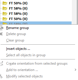
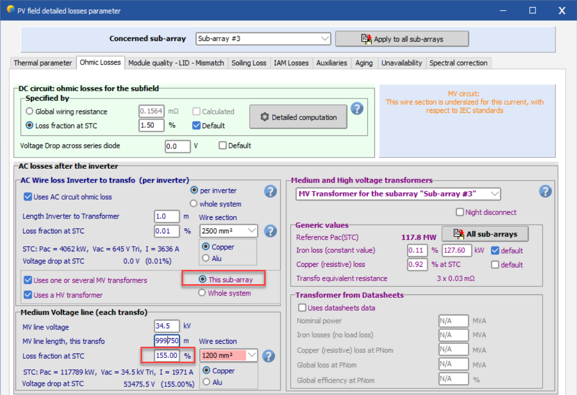
The best way would be to do everything outside of PVsyst and create manual reports. However, if you want or need to do it inside PVsyst, there are not many options. One way is to adjust the MV Ohmic loss for that subarray. Set an MV ohmic loss for just that subarray to like 155%. You will need to adjust the wire section size most likely to get the length of wire to a permissible length (there is a character maximum). This example was three symmetric blocks, I didnt fine tune the percentage loss, it is approximately 1/3 loss. Define the ohmic loss as typical for the other subarrays.
-
PVsyst will often (or always?) default to using the highest GCR under the backtracking menu if you have not selected which tracker(s) to use for backtracking, even if there are only one at say 0.411 vs 0.410. In the shade scene, go into the backtracking menu under tools to select the appropriate tracker for backtracking. There are different options, you can select an individual table (at the pitch you want) or automatic.
-
Express the report to second decimal to get clear picture, losses could be near zero and are being rounded.
-
If there are no trees or objects that shade the modules, backtracking is on, and your system is flat, it will not have electrical shading loss.
-
Increase in energy yield with azimuth different than zero
dtarin replied to Rafael Santos's topic in Simulations
No electrical shading loss is showing. If these are bifacial c-Si, you'll want to include electrical effect (modeled according to strings) and then make the comparison. -
Manually move the modules and objects over the image and line things up that way
-
Add an object in the PVC file like a tree line or houses
-
-
GlobInc = POA