
Michele Oliosi
-
Posts
814 -
Joined
-
Last visited
Everything posted by Michele Oliosi
-
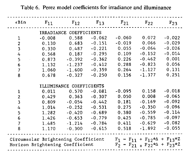
The horizontal diffuse is decomposed in circumsolar, and isotropic diffuse components according to F_1 (clearness, brightness, zenith angle) from Perez et al. 1990, Modelling daylight availability and irradiance components from direct and global irradiance: https://www.cuepe.ch/html/biblio/pdf/perez-ineichen 1990 - modelling daylight (se).pdf In PVsyst the horizon brightening obtained via the DiffuseHI*F_2 is then incorporated to the isotropic diffuse. Then the transposition factors are similar to Hay (meaning just geometry).

-
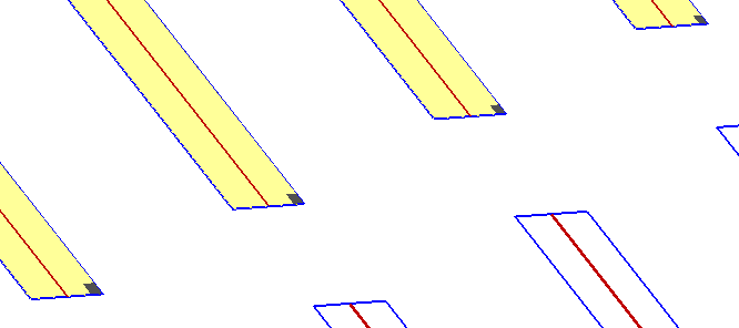
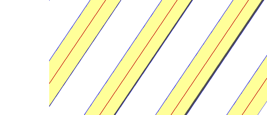
 The following types of shading patterns were typically neglected in version 7.3, and are accounted for in version 7.4 (somewhat overestimated when they are irregular, i.e. not a long mutual shading like in screenshot #2). All of these shadings are due to the topography and should not be neglected, i.e. version 7.4 should be more accurate (albeit somewhat overestimated) than version 7.3. Since these shadings are partly irregular you could consider a factor for electrical effect somewhere around 80-90% to mitigate the overestimations, but it will be very hard for us to give you aprecise value that fits the whole scene: there are many different shading instances on the scene.
-
This is likely not a bug but part of the feature. But we would need to see your scene to be sure. First of all, I would recommend checking the two following posts https://forum.pvsyst.com/topic/3085-electrical-shading-losses-in-versions-73x/ https://forum.pvsyst.com/topic/3312-electrical-shading-losses-partition-model In version 7.3, the electrical shading losses were oftentimes underestimated. Now the partition model tends to overestimate irregular shadings, which is what it was originally intended to do. For irregular shadings (not just mutual shadings), you should use the fraction for electrical effect to mitigate this overestimation.
-
Simulate Terrain-Following Tracker Systems
Michele Oliosi replied to Valerie Chan's topic in Shadings and tracking
Actually the trick used is a bit more complicated. It involves calculating the POA irradiance that trackers would yield and then simulating with that POA irradiance. This is because at the moment it is not possible to import tracking angle data through the MET file directly, one needs to trick their way out of the problem. -
"Limit shading" profile angle
Michele Oliosi replied to Dominik Damberger's topic in Shadings and tracking
Thanks for the remark. Yeah if you consider modules that are less sensitive to shadings (such as half-cut modules) the optimum may change. This page has been written some time ago so I am not surprised it may need an update or two. -
Simulate Terrain-Following Tracker Systems
Michele Oliosi replied to Valerie Chan's topic in Shadings and tracking
Because these terrain-following algorithms are proprietary, at the moment PVsyst cannot model them. PVsyst will at the moment always apply the same tracking angles to the whole scene, to the exception of tracker axis tilt differences which will induce some partially adaptive behaviour. For very irregular topographies, you may change manually the parameters used by PVsyst to backtrack. In the 3D scene > backtracking management, you can manually adjust the top and bottom frames of the tables (increase them), which makes the backtracking a bit more conservative. Finally, some people use a method in which they create a new MET file using the tracker angles they have received from the tracker manufacturer. I believe people at Nextracker may help you with this, or some people on the forum may be able to use this procedure ? -
For one pair of orientations, you should choose mixed 1 and 2. For the other pair, you need to play with the multi-MPPT power sharing options. This only works if the modules in orientation #3 are connected to a different MPPT than orientation #4. If so, you can make two subarrays, each with a different orientation (#3 and #4). You can then use the "orientation power sharing" (second tab in the "power sharing" window) to assign MPPT inputs to the same inverter.
-
Version 7.4 features novelties in the way the electrical shading losses are computed in the partition model. Here is a short recapitulative summary of the different ways the model worked in the past. ------- Up to version 7.2, the partition model has been implemented as an all or nothing model. Tables were split into partitions, i.e. PV areas that would be electrically affected by a shadow, via mismatch effects. Shaded partitions would produce power only up to the diffuse irradiance, and their direct irradiance contribution would be considered naught. ------- Version 7.3 introduced the notion that if shades were small, then these mismatch shading losses would be mitigated. However the implementation was only well adapted to very regular arrays, with a single orientation. In other situations, the electrical shading losses were underestimated. The following post details the possible issues with this particular model: https://forum.pvsyst.com/topic/3085-electrical-shading-losses-in-versions-73x/ ------- Version 7.4 takes the idea of small shading mitigation further, in that the shade on each PV table is evaluated to estimate whether or not the electrical shading losses will be mitigated or not. In this way, the cases that were not well treated in version 7.3 (underestimation in case of irregular shadings, or multiple orientations) are now handled properly. In practice, the partition model in version 7.4 splits each partition into three areas: A central area that follows the all or nothing model: if shade reaches the central area, the direct irradiance contribution is considered lost. Two lateral one-cell-wide strips, over which the full shading losses are proportional to the shaded area. In the case of regular shadings that affect an entire row of modules, this translates well into the notion that whenever a single cell per submodule is partially shaded, the production of the submodule is lowered proportionally to the shaded portion of the cell (current limitation in a string of cells in series). More details on the model itself can be found here: https://www.pvsyst.com/help/near_shadings_partition.htm For more details on how to configure that partition model in a PVsyst project, see this help page: https://www.pvsyst.com/help/shadings_partitioninstrings.htm
-
PVC Shade Scene Differences in Losses
Michele Oliosi replied to Valerie Chan's topic in Shadings and tracking
Part or most of the differences may come from the diffuse shadings calculation. With large scenes I would advise to always go through the 3D scene >Tools > Tracker diffuse shadings definition tool. Here is a help page that should cover this topic: https://www.pvsyst.com/help/tracking_diffuse.htm -
Is it possible to get a CSV file with all the simulation parameters?
Michele Oliosi replied to RobSolar's topic in How-to
Dear RobSolar, No at the moment this is not really possible. We have had a similar suggestion by various users recently, so we will try to address this issue in the future. -
Possible error in the Performance Ratio´s help section
Michele Oliosi replied to allanfisica's topic in Suggestions
Dear @Hossam you are right and I was mistaken. When looking at yearly values the PR and PRTemp should agree. We need to track down the mistake here. -
Only if the different strings are on different MPPT inputs. At the moment PVsyst won't handle inputs with different lengths of strings.
-
In terms of simulation, if the parameters are similar, the losses should be similar. Trying to get the two values to agree I would suggest the following: First of all a few things to check: If you are using the "fast" mode i.e. using the table, go to both shading factor tables (Near shadings > Table) and click on recompute. We have seen a few bugs where an incorrect older shading factor table was not recomputed automatically. If you can, use the "slow" mode (recomputed at each simulation step) and check whether the discrepancy still exists. Sometimes the shading factor table doesn't have enough resolution especially with complicated shadings. Nothing beats a visual check. You can use the shading animation for a day in winter to visual differences for a day in winter for example. Electrical shading losses are in yellow. You may find that shadings have different patterns in the two variants. If the differences persist, there may be another external reason / bug / parameter choice not listed above. You can send both projects at support@pvsyst.com we'll gladly have a look. Now I should make a comment about first solar modules vs Jinko Solar JKM400M-72HL-V and partitioning in general: The two modules have very different technologies, and they respond to shadings in different ways. Jinko solar is a half-cut cells module and when in portrait, you should partition it with two partitions (in height) per module row. On the other hand First Solar modules are thin film modules that are quite resilient to shadings as well. When installed in portrait, they will not suffer much from inter-row shadings. If shadings are only inter-row I think they advise to deactivate electrical shading losses, by using "linear shadings" instead of "according to strings" in PVsyst. Since you have other shading objects such as trees etc, which give more vertical shadings, I would suggest keeping the "according to strings" and lowering the fraction for electrical effect, for example to 30%. I would suggest sending them (First Solar people) an email for detailed guidelines, I am not too sure of how to determine a good fration for electrical effect in this case. Maybe someone on the forum has some info for First Solar modules in complex shading situations ? In general for partitioning, you can check the help page: https://www.pvsyst.com/help/shadings_partitioninstrings.htm we will be updating these pages again soon, but they already offer some guidelines for partitioning.
-
Confused tables when importing a PVC scene
Michele Oliosi replied to Nicolas T's topic in Shadings and tracking
The risk is that some tables are constantly shaded throughout the simulation if they touch. In general though, the safety margin by PVsyst is quite ample so you can try disabling the interpenetration check as you did. Just make sure to compare results just as you did. We noted the issue about moving things one by one, we will try to improve on this point. -
IRREGULAR PITCH: HOW TO IMPLEMENT THE BIFACIAL CARACTERISTICS
Michele Oliosi replied to C. Amorevole's topic in Simulations
Hi, Thank you for the different comments. First of all, I am not sure that "partial shadings group" will help in your case. Indeed, it allows to take calculate the frontside shading factors using only part of the tables, but has no impact on system or orientation. If there are two nominal orientations in your scene, even though you use the partial shadings group, in "Orientation" there will still be two orientations. If I'm not mistaken the pitch used by the bifacial is still the average of the whole scene as well, not only the partial shadings group. Second, the bifacial model is limited in its use to a single orientation in "Orientations". If you want to avoid the issue of using the average orientation, you will have to do two different variants, each with its shading scene containing only the objects from group 1 or group 2, respectively. In future (long term) major version v8 we will link the bifacial model to the orientation so you don't need to split in two variants. But this is still in development. Changing the pitch rms limit serves the purpose of bypassing the error message in PVsyst and proceed by using the average pitch even though your scene has several pitches. So there is no direct effect on the simulation results. Again thanks for the comments and sorry for the complications for this kind of scenes. Your post will definitely help making PVsyst better in the future. -
Simple Flat Terrain, Domes Installation with Bifacial Modules
Michele Oliosi replied to KevinS's topic in Simulations
Sorry, at the moment there is no way in PVsyst. We have plans to improve this eventually. Even with rows of a single orientation the gain is ~5% (10% if ideal), so I would expect little gain for domes e.g. 1% or even less. -
Bifacial Module Simulation with different tilts & azimuth
Michele Oliosi replied to sajid s46's topic in Problems / Bugs
So far, the only way is to compute it manually. Solar fraction is defined as EUser / ELoad, so you can use the total EUser and total ELoad instead. -
Possible error in the Performance Ratio´s help section
Michele Oliosi replied to allanfisica's topic in Suggestions
Dear Hossam, I would say this must be a coincidence, (taking the demo projects you can find different examples). Are you using the same weather data ? -
Possible error in the Performance Ratio´s help section
Michele Oliosi replied to allanfisica's topic in Suggestions
PR and weather corrected PR are not the same of course, so they shouldn't be equal in general. Or do you mean you find a difference between your calculation and the PVsyst calculation? The issue has been fixed and you can follow the help page to see the formula ? Edit: in fact you are right, there seems to be still a small mistake. the PR and PR corrected for temperature should be the same for the yearly value. We will track down the error. -
Sure, if you select custom tracker only that tracker (green) and the shading ones (orange) will be considered. Sorry in my previous answer I meant "if the threshold number found in the advanced parameters (default 40, but you may have changed) exceeds the total number of trackers in your 3D scene" + having selected "automatic". If you select custom tracker this will override the "automatic" setting.
-
Since the performance ratio is normalized to the plane irradiance, each month is not equivalent. The total PR should be a weighted average according to GlobInc.
-
Hi ! Thanks for the interest in this feature. Yes we are working on implementing that in PVsyst ! We will be trying to release it this year, but it's not possible to be more specific at the moment.
-
Hi, The interface is currently a bit unintuitive, but before clicking apply you should be able to check the radio button (the left circle) in front of "All tables of the scene". Clicking then on apply should then turn the checkbox automatically on.
-
If you have selected the option "all trackers" or if the threshold number found in the advanced parameters (default 40, but you may have changed) exceeds the total number of trackers in your 3D scene, the diffuse shading factors will take some time since all trackers will be used for the calculation. The time it takes depends drastically on the complexity of the scene and shading objects.
-
Bifacial and Monofacial Panels in a same system
Michele Oliosi replied to Omama Zaheen's topic in Simulations
Sorry, at the moment it is not possible to have both monofacial and bifacial modules in the same system in PVsyst. This will be addressed in the future.