
Michele Oliosi
-
Posts
824 -
Joined
-
Last visited
Everything posted by Michele Oliosi
-

Bifacial modeling with shading scene
Michele Oliosi replied to Pranav Maheshwari's topic in Problems / Bugs
Hi Actually, this is a misconception shared among many users. You can simulate with the bifacial model and a 3D shading scene ! However, there are conditions on the shading scene for this to work https://www.pvsyst.com/help/bifacial-conditions.htm The main issue in your case is that you don't have multiple rows of tables, but just a single row. Besides, the tables are not the same width. This will prevent from using the bifacial model jointly with the 3D scene. I would suggest the following: Make a variant without the small table. Replace the other 11 modules by a single 6 by 2 table. Duplicate the whole scene and place the copy far away to the northwest. This will mimic a second row and trick PVsyst to let you use the bifacial model. But because the second table is so far away, they won't affect each other. You should use the shading mode “according to module strings”. Because the number of modules is not the original one, using the detailed electrical calculation is not possible. -
Natural or forced air circulation. If the modules and roof are flush: fully insulated If there are a couple centimeters between modules and the roof : semi-integrated
-
Electrical loss according to string - Tracking systems
Michele Oliosi replied to gpuy's topic in Shadings and tracking
In the end, the results were consistent with the backtracking (on flat ground, therefore ShdElec = 0). So no issue after all. Did anyone experience the same issue ? Or were you following by interest ? -
Basically, if there is no air circulation at the back of modules.
-
If the modules have some air duct at the back, it should count as semi-integration.
-
As far as I know, without further documentation, I would suggest using the default values. However, if you have detailed information about your module (from a lab for example), you can use that.
-
Yes, currently you can mix only two orientations, so indeed, if you have 3 orientations or more, you should artificially add MPPT inputs to your inverter.
-
orientation Error on Simulating Multi Orientation Module
Michele Oliosi replied to Asyraf's topic in Simulations
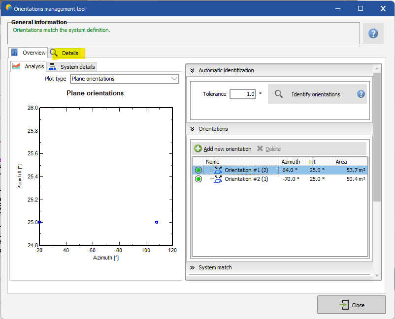
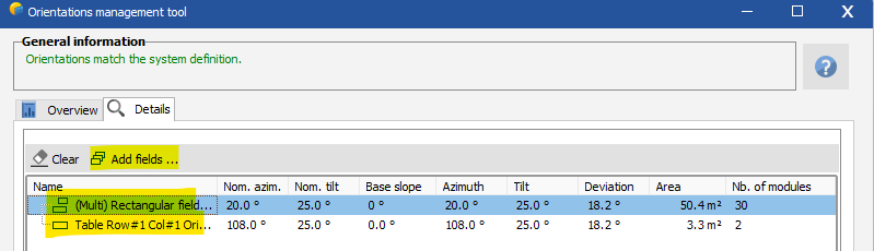
Hi, First, I understand you want to distribute a string on two orientations ? This string 2 is not possible to implement in PVsyst. Indeed, PVsyst does not support strings that have modules in two orientations. I think the easiest is to consider the average orientation North+West. Since there are only two modules that are towards the West, this approximation shouldn't be too bad. I have made a similar example. Note how there are two orientations only. I started by eliminating the orientation with few modules, clicking on delete. Then select the orientation you want to group the few modules in, go to "Details", and then "Add fields" and add the modules. In this way you will end up with two orientations. Now string 2 can be in a single orientation.
-
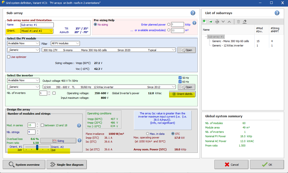
Yes, it is possible. In the sub-array with the central inverter, you should use the “Mixed #1 and #2” orientation. Then you can distribute strings using the slide bar at the bottom, or the tool “Orient distrib.”. For example (using the DEMO residential, and modified):
-
Electrical Effect in Simulation - Unlimited Shades
Michele Oliosi replied to Michalis Angeli's topic in Simulations
Hi, yeah, it is recommended to use the electrical effect functionality. Indeed, it is only with it that you can fully take into account the effects of shadings and mismatch caused by shadings. The width of the PV cell should be the width in the height of the table. For example, for an 9 cm by 18 cm cell, in a half-cut module in portrait, the relevant height is 9 cm. The number of modules is an old name for this parameter. Now it is best read as “number of partitions in the height of the table”. https://www.pvsyst.com/help/shadings_partitioninstrings.htm -
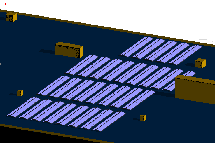
This type of two-orientation structure: How do you usually call them ?
-
I see. The number of inverters in the configuration is 147, so none of the subarrays has a #MPPT multiple of 147. You will need to be more specific with your assignments of strings -> MPPT -> inverters. Each configuration should be an identical type of inverter. For example, if 25 inverters have the same configuration: 3 MPPT of type 1, 2 MPPT of type 2, and 1 MPPT of type 3, then that would be a configuration with 25 inverters. For each of these configurations you should create the necessary sub-arrays. In the same example, you need a sub-array with 25*3 MPPT of type 1, another of 25*2 MPPT of type 2, and another with 25*1 MPPT of type 3.
-
Dear Chae Han Lee, At the moment, it is not possible to simulate a mixed orientation in a single string. By the way, doesn't that cause important mismatch losses within the string? For the other cases (mixed orientation in a central inverter) that is possible, as long as each string has a given orientation.
-
@J. Behrschmidt the requirement that the #MPPT is a multiple of the inverter number is necessary in order to fully define which MPPT goes to which inverter. As in the example above: What this means is that in reality you don't have just 1 configuration, there are 2different configurations in your settings.
-
If you have cable length and conductor type, the best is to use that information directly. PVsyst will then compute the resistance of your cabling. STC is 1000W/m^2 and 25 °C so yes you have to take that into account if you want to enter a percentage loss value. I would rather recommend using the cable length, section, and conductor type instead.
-
Import PVcase Tracker Layout with Gaps
Michele Oliosi replied to audlau's topic in Shadings and tracking
I see no reason why it shouldn't be possible. But please let us know if it doesn't work out. -
As a side note, a TMY is not the good place to look for a minimum temperature. You should look for a minimum temperature over many years of time series data. The TMY is a snapshot with a biased take, aimed at representing an average year. Currently, there is no way to change the maximum limit of 30 °C. The only other way is to modify the OND, and to manually set up the absolute maximum voltage to a higher value. We do not recommend it, but it has been done by some users.
-
Hi the issue here is that with these two configurations, it is not possible to know how the MPPTs are distributed among the different inverters. For example, for configuration 1, there are 2 inverters, but you have 11 and 13 MPPT to distribute, so there could be (11+1 and 12) or (10+2 and 11+1) or... For this reason, we ask that in each sub-array, the number of MPPT is a multiple of the number of inverters in the configuration it belongs to. Despite the complicated premise, resolution is easy: you should split your sub-arrays further, so that you satisfy the requirement. For example, in the case of configuration 1, you could split the sub-arrays into: - sub-array "west facing opt" split in west facing opt 1 with 11 MPPT and west facing opt 2 with 2 MPPT (total 13) - sub-array "west facing 19pc" split in west facing 19 pc 1 with 10 MPPT and west facing 19 pc 2 with 1 MPPT (total 11) This would give you two configurations instead of one: - 1.1 with 10+2 and - 1.2 with 11+1
-
Yeah that's the gist of it !
-
Can you consider that there are 2 strings of 28 modules on each MPPT ? That should be equivalent.
-
Solargis csv file to PVsyst for creating a MET file
Michele Oliosi replied to Leon's topic in Meteo data
Each simulation needs 1 site (SIT) and 1 hourly weather data (MET) as specifications. The SIT is used mostly for the geographical coordinates, and some other details, to properly simulate the sun geometry. The MET is used as the main source for irradiance, temperature, and other hourly weather variables. When working on a project, you can specify both of them. There are several types of MET files. A synthetic file (SYN) is used whenever you want to generate a typical year of data, from monthly averages. However, you can also directly use time series files (the 15 you have generated) as input for the simulation. Finally, you can also generate a TMY from the time series, and use this TMY as an alternative to the SYN. Both represent a “typical” weather.
-
As mentioned above, it is not directly possible at the moment, sorry. You could estimate the bifacial gain using a single orientation, replacing each EW dome by a single horizontal PV table with the same width as the original EW dome basis. However this is an extremely crude approximation.
-
Usually the weather data provider will provide the variability. It is already included in most TMYs on the market. For the climate change it is a bit more complicated. If you have a specific year of a time-series, you can ask yourself whether this year is above or below average and by how much (in terms of irradiance). For predictions we actually do not really know how to do this, an idea would be to look at multi-year trends for the location. Both are indeed used for P75 and P90. The P50 is controlled by the climate change % only, to shift the simulation value. You can use the aging tool (advanced simulation > aging tool) which allows you to simulate several years in a row and present the result in a formatted table / report. a 25-year-P90 is a concept we haven't implemented in PVsyst yet. You should not concatenate 1-year P90s, this approach is incorrect. Indeed, when taking longer sampling periods, the weather variability should decrease, by a factor 1/sqrt(n years) approximately. But note that the uncertainty does not decrease over the years. In practice after 25 years, you may get more or less 1.5-2% of variability + uncertainty.
-
in this case you should space the EW rows sufficiently to get try to get some ground reflection
-
It is not currently possible to simulate with PVsyst as this has two orientations (we handle only one for now, we will update this but not before 2024 I think). However the bifacial gain is usually negligible (there is no light arriving on the backside), unless the domes are high enough over the ground.