
Michele Oliosi
-
Posts
824 -
Joined
-
Last visited
Everything posted by Michele Oliosi
-
The approximation will probably be slightly optimistic for the bifacial gain. There is a way to not change your 3D scene tilts, it would be to go to the 3D scene > Tools > Orientation management, increase the tolerance (more than 20°) and click on Identify. In this way you can trick PVsyst into considering only the single average orientation with tilt 0°. The transposition gains for the front side will however be a bit off.
-
As mentioned, the warranty information (that you can enter on the bottom right of the window) will not affect the simulation, it is just indicative ! The orange curve (sum of average degradation factor and mismatch increase due to degradation) should generally stay above the black curve (warranty), to be realistic. If you really want to study a degradation = to the warranty, I would suggest entering 0 to both RMS values, and 0.55%/year in the "Aver. degradation factor". But I don't know why you would like to do so.
-
 In your situation, the issue comes from having multiple orientations. PVsyst has currently some trouble handling imbalances between MPPT powers when they are both due to a difference in nominal DC power, or differences due to the orientation which causes the power to shift from a string to the other. The most critical is the case of configuration 1. I would suggest not to use the multi-MPPT for these 2 inverters of configuration 1. You should instead define a single orientation with 2 inverters while disabling the “multi-MPPT feature”. You can then define the orientation as “mixed orientation”. There is a cost, however, in that you should define your strings as either all with optimizers or without optimizers (I assume that is what OPT means). This approximation is necessary to be able to have a single sub-array and use the mixed orientation feature. I think you will end up with less clipping losses. But since this case is quite complicated, please let us know the results, and we will help you with it if there are still some problems. We can also move the discussion to emails, at support@pvsyst.com, as you prefer.
 -
No, sorry, the results are not really useable like this. The backside irradiation model (bifacial model in PVsyst) is a 2D approximation that currently only works on single orientation rows. It does not take into account shading objects from the shading scene, as the roof you are adding instead of the other rows. What is the height of the modules ? Are they at ground level ? If so, you can expect zero bifacial gain. If they are on a structure that lifts the rows above ground (like on a carport) then there may be some bifacial gain. If the rows are well above ground, you can consider approximating your system by a tilt 0 flat disposition. In terms of bifacial gain, you should get an ok result.
-
Outlier treatment using non-linear regression
Michele Oliosi replied to Rafael Vilela's topic in Simulations
I don't know the reason for the -28W/m^2 specifically, but I imagine it is related to accommodating some measurements we used for the validation of the code. Physically, considering the balance of radiation at night (a clear sky has a low temperature) it is common that pyranometers give negative readings at night. For PVsyst it doesn't matter too much, since there are other “nighttime” filters that set the production to zero. Your research is definitely interesting, we'll gladly give it a read once published / made public. I am sure it may be appealing to other forum users as well. -
A warranty cannot be used in the simulation. It is a warranty, i.e., commercial information. It does not really reflect a module degradation. Besides, the downwards slope is not easily readable from the graph but would be about 0.7%/year, which, as mentioned, would be overly pessimistic if it was a real degradation rate.
-
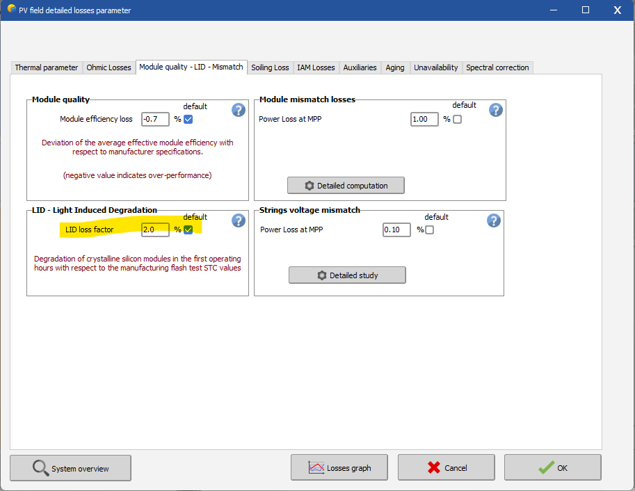
Hi, first, please be careful that the warranty specifications on a datasheet are not equivalent to the degradation factor. The warranty specifications are usually a bit pessimistic. Then, the first year degradation factor is likely due to LID of 3%. You can define an LID of about 3%, and use only the 0.3%/year in the degradation window.

-
PV System withou injection energy to grid
Michele Oliosi replied to Michalis Angeli's topic in Simulations
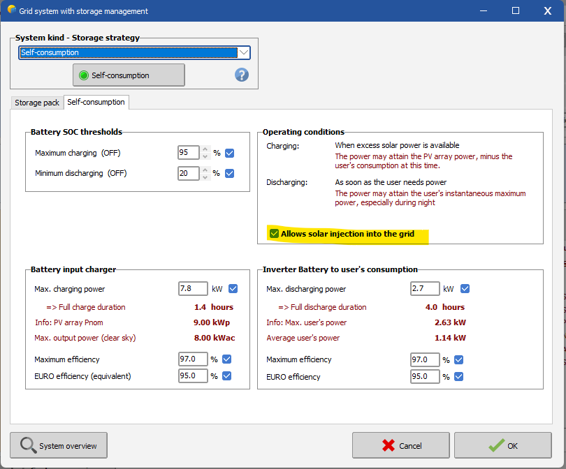
In this case please go on with "Grid connected" and not "Standalone". In the storage strategy you have the option to allow or forbid the solar energy injection into the grid.
-
The important point to clarify is what a configuration means: it is a certain number of inverters that have exactly the same strings & MPPT configuration. Among your 7 inverters, there may be a subset (for example 3) that share in the same strings & MPPT configuration. Then in the sub-arrays that refer to this configuration, you should have a multiple of the number of MPPT in this configuration (in the example 3). It is essential to separate the total number of inverters in your system, from the number of inverters in a given configuration. Indeed, this check is relatively new. However, this means that some incorrect situations were allowed in the past.
-
Outlier treatment using non-linear regression
Michele Oliosi replied to Rafael Vilela's topic in Simulations
When importing custom data, PVsyst will test whether irradiances are between -28 W/m^2 and 1600 W/m^2. If the irradiances are out of these bounds, they are considered 0. If you want to use the data in PVsyst, I would suggest using your filters for outliers before importing in PVsyst. Finally, the sine may work ok for clear sky conditions, but how do you account for overcast conditions ? -
There is the problem of sun direction, I think doing this would get that incorrectly. However you can split in several files for each minute stamp and simulate each one with the proper time shift, that should do the trick.
-
PV System withou injection energy to grid
Michele Oliosi replied to Michalis Angeli's topic in Simulations
If your system does not exchange energy with the grid, it means that the grid will only be there as a backup to cover for excess load, is that right? What about times when the batteries are fully charged? -
Can you send us the CSV to support@pvsyst.com ? We will try to find the issue.
-
Were they simulated in the same version? If so I invite you to send us the project for review at support@pvsyst.com
-
In the source CSV, can you try putting "Date" and "Load" on the same line ?
-
Bifacial modeling with shading scene
Michele Oliosi replied to Pranav Maheshwari's topic in Problems / Bugs
Yes, can follow the method. I would suggest combining your idea with my previous comment, i.e., using the 3D scene variant, but choosing only a single orientation. This would be the second simulation. It is likely a bit more precise than the simulation with unlimited sheds. -
They should be the same, if the 3D scene, horizon, MET file are the same. Did you change anything else except the inverters?
-
Hi, this is surprising. As far as the latest version goes, the backtracking works with axis azimuths different from 0°. Are you using the latest version or a previous version? You can send us your project for review at support@pvsyst.com, we can have a look.
-
PV System withou injection energy to grid
Michele Oliosi replied to Michalis Angeli's topic in Simulations
You should design a “Stand-alone system” in this case. -
Usually the default value is what is pre entered in PVsyst when you open the window. In this case, it would be 0.4%/year. You can also check the help for more details.
-
I think these were just example values. Unless you have information from a research group / lab / measurements, I would recommend to just leave the default values.
-
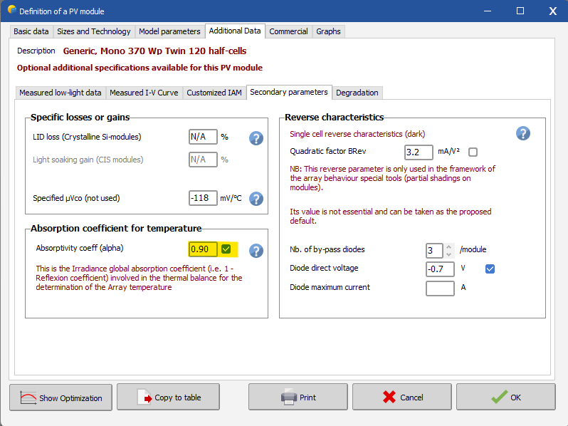
In general, it's 0.9.
-
This is coincidental, the two are not related.
-
No, as stated in orange, this is not necessary unless you are doing a very specific aging study and need a degraded module.
-
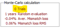
Please read https://www.pvsyst.com/help/ageing_general.htm The black values (%) are calculated from the red values (%/year). Since we calculate in the middle of the year (1/2 year mark), 0.5%/year means 0.25% for the simulation. To this, the mismatch degradation values are added, which are calculated from a series of random samples. By the way, your mismatch loss seems wrong. Please uncheck “keeps calculated mismatch values” and click on “add statistics” a couple of times. You can then resave the model.