Search the Community
Showing results for tags 'simulation'.
Found 13 results
-
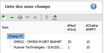
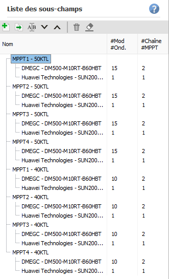
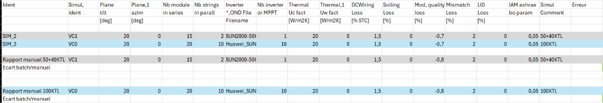
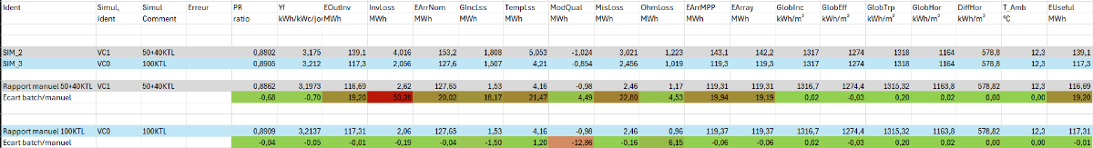
 Hi, I'm planning to do a batch simulation to test a setup in different cities. Before that I did a test with a batch of only 2 variants to check the results against a manual simulation for each of the variant. The 2 variants : Same plane, same orientation, same modules, same parameters One variant with a 100KTL One variant with a 50+40KTL 100KTL 50+40KTL The losses in the batch params are the same as the ones in the detailed loss. Do you have an idea about the following things : Why is there a difference between the module quality for the 100KTL variant ? Do batch simulation work with multiple inverters ? Is it normal to have variation between batch simulation and manual simulation ? Thank you
-
Hi guys, I'm making a simulation based off a real system that uses a 2.8 kWh LifePO4 Battery which is a lithium iron phosphate battery. this battery isn't on PVsyst so i need to create it manually but PVSyst also only has Lead acid and lithium-ion batteries. Are there any batteries on PVSyst or in general that I can use to replace the 2.8 kWh LifePO4 battery. The battery is manufactured by PRIME
-
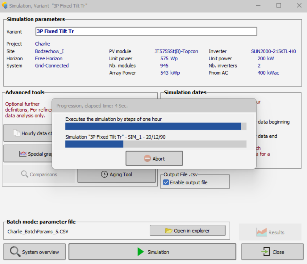
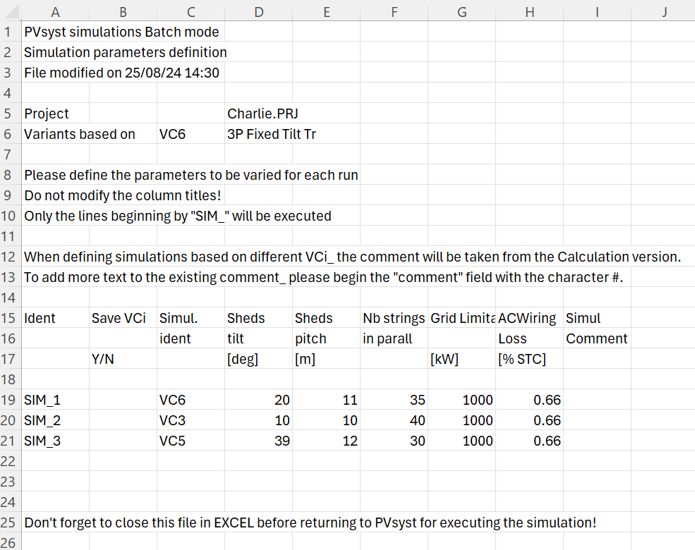
 Hello Everyone. I have an issue with using a feature of different simulation variants in the butch simulation. I want to make one batch simulation for my whole project and choose "Start from different VCi base files" in the batch simulations section. So, I configure batch simulation from the menu with the set simulation VC6 in the project's window, for example. I enter into the Excel parameter file what I want to produce calculations with simulations VC3 and VC5 as well. But, after the corresponding option (BC6) is calculated, the PVsyst hangs. After pressing abort, also no changes and I can only close the program through the task manager. Of course, I checked the possibility of errors within the simulation options and other trivial reasons, unfortunately, I did not find a solution below. I also attached a screenshot with the described parameters of the batch simulation and the moment of freezing to the post. Please tell me how to resolve this. Thanks in advance
-
Hello, I have a question. when I determine the maximum number of panels in the string, I follow the default of -15°, but sometimes this value in the cold season (usually a few days a year) can be lower (usually at night), can this approach disable the inverter?
-
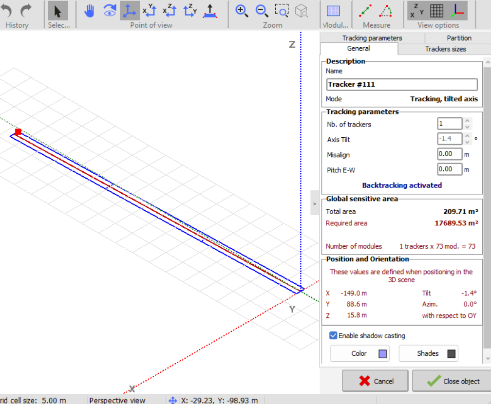
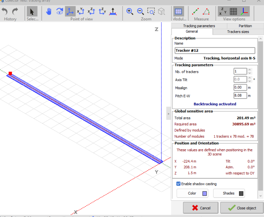
 PVcase imported trackers do not have pitch defined when going in the modify object. Does it impact backtracking? I have heard from a few industry people that it does not do the backtracking as it does not have the pitch defined (or not an array of the trackers) and all the trackers are ungrouped and are not an array of trackers Also if I ungroup an array of trackers which was created in PVsyst near shading, does this affect the backtracking? See the below snip for reference Pvcase export An array of trackers was created in Pvsyst and then ungrouped
-
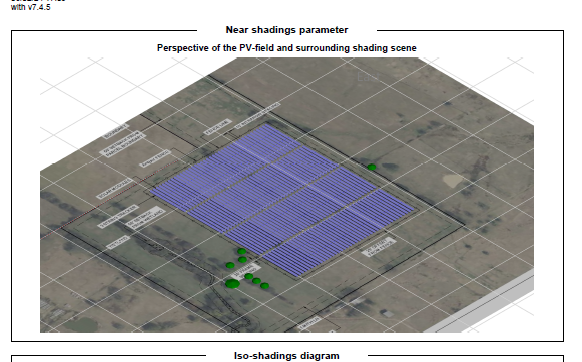
Imported ground image is coming in the report even after decreasing the opacity to zero in near shading. It only does not show in the report for the first time. When opened next time report has image included.
-
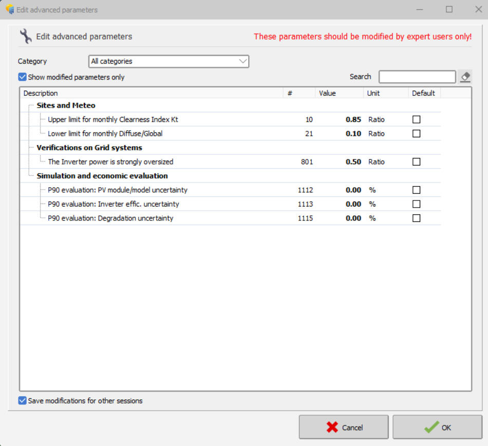
Hi Team I have edited the advanced parameters in the past for one of the clients but forgot to make it default parameters for other simulations. How much this might have affected the overall production estimation? Thanks in advance.
-
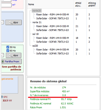
im only using 4 out of 5 mppt, and in "number of inversor" is just 0.8, not even a full inversor, does it make diference on the simulation??
-
Hello forum users, i am doing some research on the various Horizon sources available. i have chosen some meteo data i have used for previous projects and i would like to do a series of analysis for each one of them using: 1 - SolarGIS Horizon profile 2 - Meteonorm Horizon (from PVsyst web sources) 3 - PVGIS Horizon (from PVsyst web sources) my goal is to: compare the "far shading losses" and the Horizon line drawings considering the different Horizon data so to have a general overview of the differences between the Horizon datasets; of course my research will also include the study of the manuals and theory behind the definition of the Horizon profile provided by each one of the three Meteo database. i would like to raise a couple of questions: how far has to be an obstacle to be actually considered in the far shadings? considering the high dependency of the horizon from the exact geographical coordinates, are there any suggestion on the horizon profile choice regarding big PV plants? has someone of you undergone some similar studies? have you found some interesting results? also, considering point 2, a question for the software developers: are you considering a possible software update that would allow the user to set different horizon profiles, perhaps linking a single profile to a single subfield? thank you very much in advance for your contribution! Davide
-
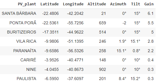
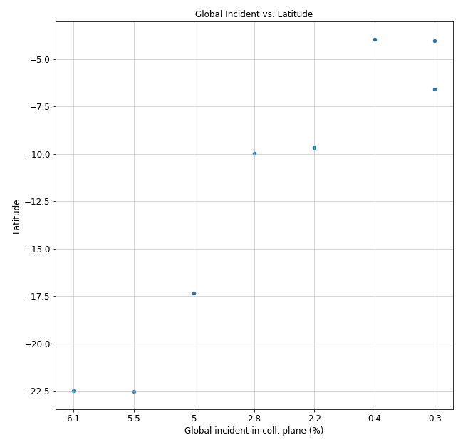
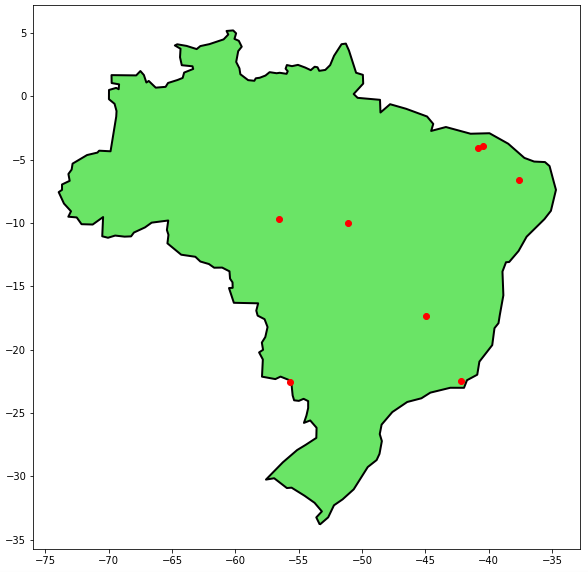
 Hello, everyone. After running a few simulations on several sites of the Brazilian soil, I realized that the Global incident in Coll. plane from the Loss diagram was very different on each simulation. Since all of my simulations have fixed sheds, not trackers, I started wondering why in some cases I got over 6% Gain on Global incident in Coll. plane and others I got only 0.3%. Even if I used the optimization tool for tilt and azimuth enhancement, the Global incident in Coll. plane would not change significantly. The only correlation I could find for this behavior was with the Latitude: The closer I get to a 0° Longitude, the smaller the Global incident in Coll. plane is. This trend is clearly shown in the following table and scatter plot: The column 'Gain' represents the Global incident in Coll. plane value taken from the simulation's Loss Diagram For a visual reference of where those simulated plants are located: Given all that explanation, I have some questions: Is my interpretation correct and the closer I get to a 0° Latitude the smaller the gain for Global incident is? Can you recommend me articles that explain this behavior, either on PVSyst or a more general sense? Why couldn't I get a significant enhancement of the Global incident in Coll. plane when I used the optimization tool (for tilt and azimuth)? I hope you can help me with those questions, and I'm available for further discussions. Best regards.
-
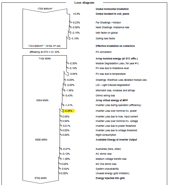
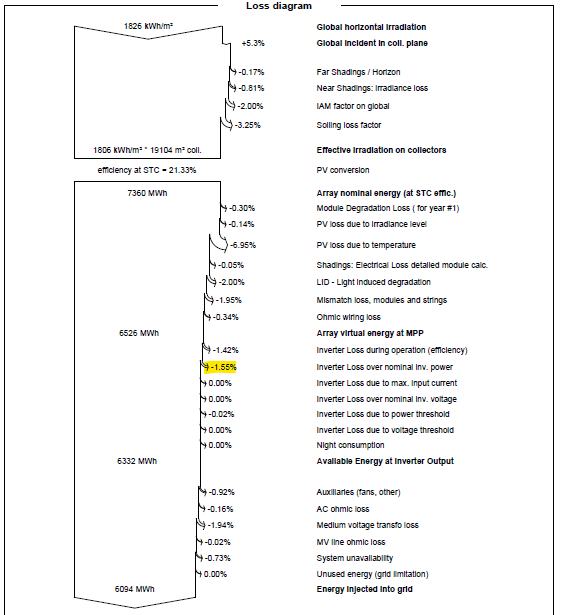
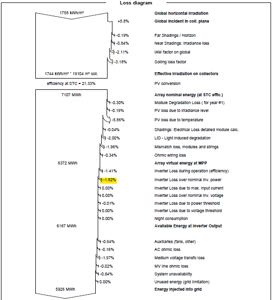
I've ran two simulations, both of them are a 3MW (12 x 250kW inverters) and 4,066MWp array, two different sites. The first simulation, let's call it Plant 1, I got the value of -4,06% Inverter loss due to nominal inverter power. The second plant, Plant 2, with the same inverter and array configuration, I got the value of only -1,82% loss. Plant 1 Plant 2 When I spotted this difference I figured it could be due to the respective plant sites, which are distinct. So I inverted the sites in both simulations, but it didn't make much of a difference: It's noticeable that the inverter temperature loss changes properly, but the inverter loss duo to nominal inv. power is about the same. Plant 1 - Inverted site Plant 2 - Inverted site I can't figure out what exactly is causing this Inv. loss duo to nom. inv. power, but it's certainly about each simulation's parameter. Can somebody help me with this issue? What parameter could be causing this significant difference?
-
Hi all, I want to know how PVSyst calculates TArray (for monofacial and bifacial modules) As I can see in: https://www.pvsyst.com/help/thermal_loss.htm 0) This is the formula that uses PVSyst. Is it right? 1) Tcell is TArray? 2) U = to the value introduced by the user (for instance U=29 W/m2K) , or U is calculated (ignoring the fixed value introduced by the user)? 3) Alpha is always 0.9? 4) Ginc: Which variable is? Ginc = GlobInc ? Ginc =GlobEff ? Ginc = (GlobInc + GlobBak) ? Ginc = (GlobInc + BifacialityFactor * GlobBak) ? 5) Effic is always 10%? I enclose different calculations I have made and the differences between calculations Thank you in advance for your valuable support.
-
 Hello, I am using PVSyst version 7.2, I have created a template meteo file that contains irradiance (w/m2) and ambient temperature (c) iwhich I import as a custom file into PVsyst with an appropriate conversion protocol file (MEF). The imported file contains hourly expected data for the whole year (8760 hours) with only 24 hours changed to actual values representing the actual temperature and irradiance values of the day I'm considering that come from the sensors at site. In some cases, values for the amb temperature and irradiance are 0, which should result in PVSyst simulating no energy production during that time interval, however when performing the simulation and extracting the output file I notice that the amb temp and irradiance values for intervals that were inputted as 0 have changed and become positive and therefore pvsyst has simulated energy production when there should not be. Has anybody faced similar problems or might know a way around this?