JGM
-
Posts
9 -
Joined
-
Last visited
-
I don't why I posted this question on "suggestions forum", it shall be on "PV components" may be. My bad.
-
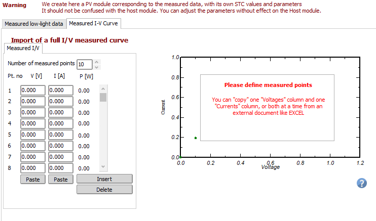
Hi, I am triying to include some additional information on a PAN file from a measured I-V data @STC (1000 W/m2, 25ºC). I would like to confirm one of the following points: Is it possible to save the imported measured I-V Curve data on the PAN? I tried several time to save the information but each time I save the file, this graph shows no data at all. Or: Is this "Measured I-V Curve" an educational tool to estimate Rsh & Rs of the PV module and no I-V curve information will be save on the PAN file? In any case, which shall be the best way to use this "measured I-V curve" to reestimate the Rsh and Rs? 10 points considering from Isc up to Voc? Or 10 points considering from Isc up to Pmpp? Or 10 points considering from Isc up to an intermedian Point between Isc and Pmpp? Thanks in advance,

-
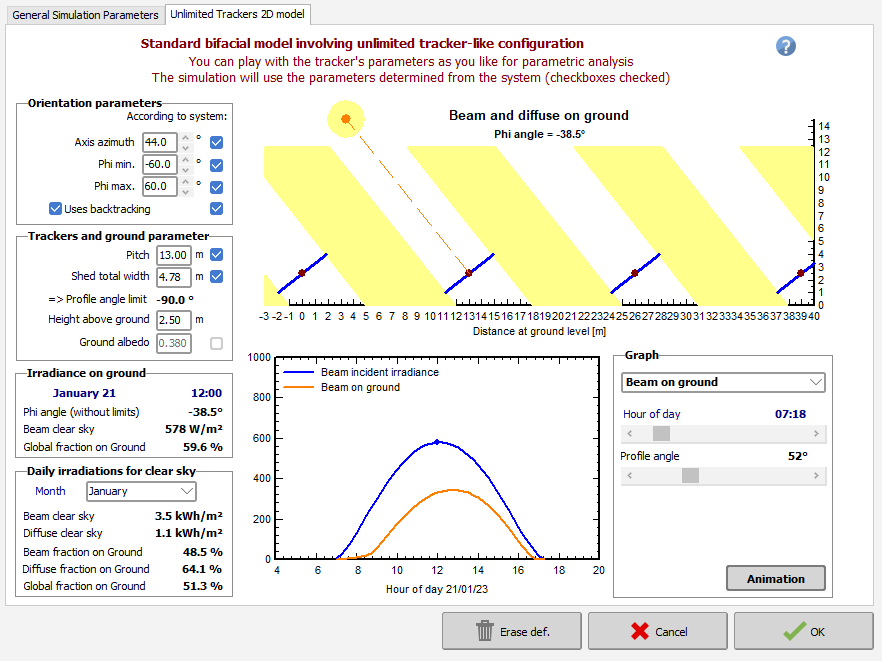
Hi again, Talking about the bifacial model parameters, I got two questions: First one: my 3d-scene has 22º azimuth orientation but the axis azimuth in the bifacial orientation parameters is 44º. Will this affect the calculus? When I update the value to 22º and I close the window, the axis azimuth change to 44º again. Second: I think that it would be really useful to have an additional parameter related to the following inputs: Minimum gap with the ground. The maximum/minimum phi of the modules. Height above ground. Two of this parameters shall work as the restrictions and the third as the output, for example: If you are considering a 0.5m as gap with the ground and +-60º of tilt, then you'll have a minimal height above ground according this two restrictions. On the other hand, if your exercise considers 0.5m gap with the ground and you are trying to set a height above ground too low, PVsyst should correct the maximum/minimum phi to avoid ground colision. Should it be possible to add this? Thanks a lot.
-
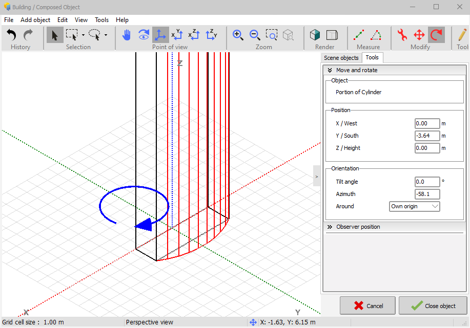
Hi again, I checked the forum looking for this topic but i coulnd't find anything similar Regarding 3D objects modeling, we only have 2 planes rotational options: - XY plane as "azimuth" - YZ plane as "tilt angle" For building/objects 3D modeling is a bit complex when you want to generate a custom geometry so, I think that it would be really helpful to have a third rotational plane (XZ plane). Would it be possible to add this? Thanks a lot
-
Hi André, thanks for your reply. Understood.
-
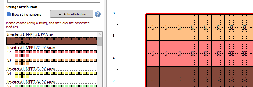
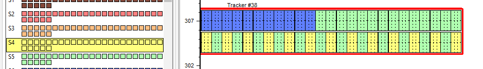
On the other hand, I'd like to ask if it's possible to select the MPPT for each string. If I would like to arrange the String 1 and 2 in the same MPPT, how could I do it with Module Layout? Thanks.
-
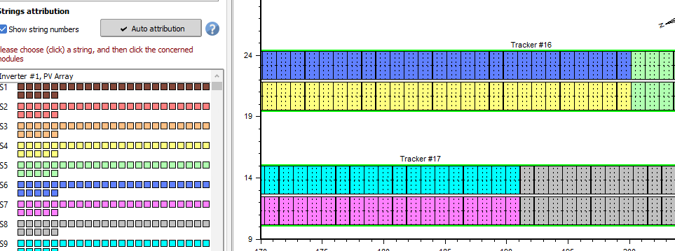
Greetings. I started to work with the module Layout tool recently and I saw a problem regarding with the strings color. I use to work with glasses and after some hours is really difficult to distinguise colors with similar constrast. If you are working with the auto attribution there is no problem with the colors, but if you need to do a manual redistribution of these strings (yellow one and clear green one for example) for me it would be more difficult to see the modules of each string in the table. Is it possible to modify the color of each string? If so, where? If not, It would be possible to add an option of high contrast colors in Module Layout? Thanks.
-
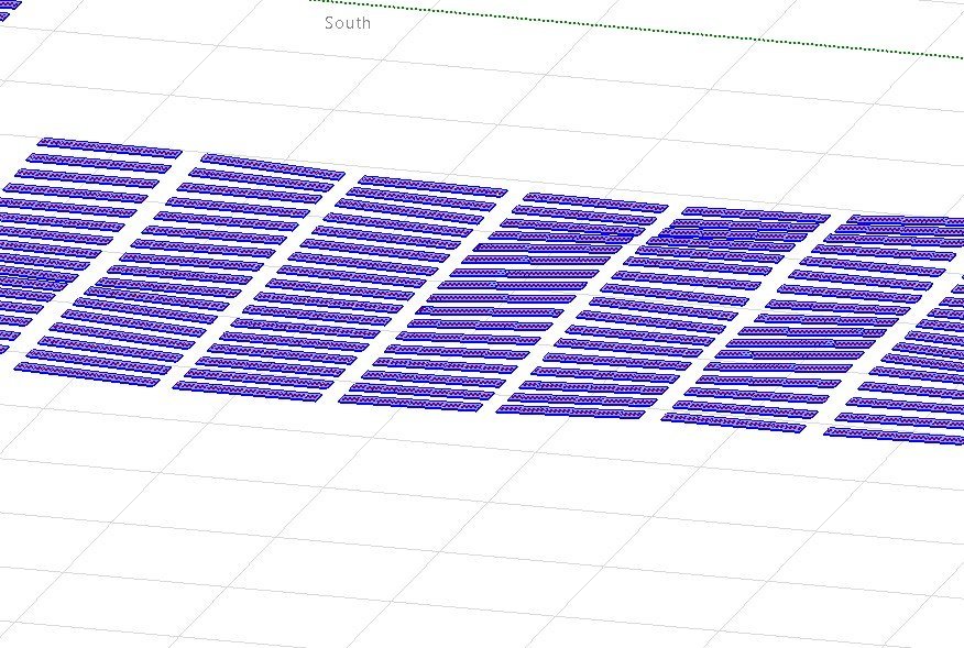
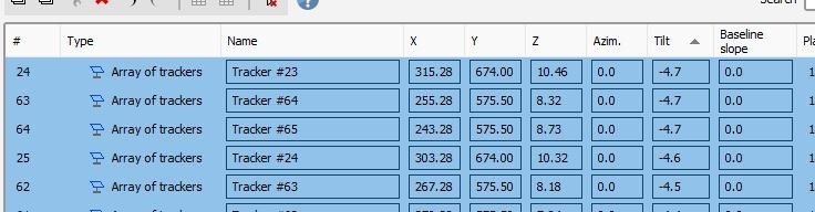
Hi to all community, I am performing a simulation with N-S Trackers with several tilts according to the terrain and including backtracking but I would like to confirm some points related to 3D analysis and energy calculus. The mimum tilt is -4.7º and maximum 6º and average tilt of PV field is -0.7º. First of all, I would like to confirm if the GlobInc, energy array and field energy, at least from the point of view of front side of module, is calculated according each tracker tilt as occurs with the 3D shadding losses, or if only average field tilt is used to regroup the trackers to evaluate these outputs. From the point of view of rear side and bifaciality, I understand that current model only evaluate the field as horizontal modules, is that correct? Is it expected a future update about this methodology? Also I would like to add some terrain elements to the scene. Does PVsyst has a limit on number of elements of that kind? Related to the current limit of +-8000 points, could I add two csv file terrain with +-8000 points each one or the +-8000 points is a limit for complete scene? Thanks to all beforehand.