Aaron3707
-
Posts
6 -
Joined
-
Last visited
-
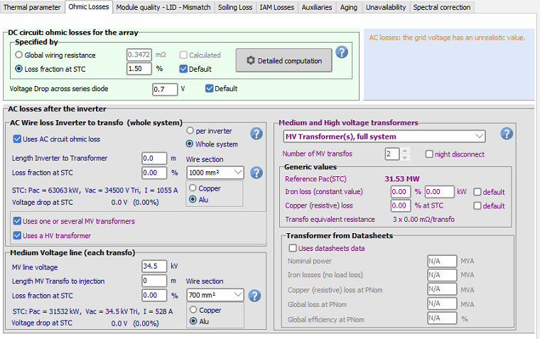
First time trying to simulate a PVsyst using an OND file that already accounts for the MV portion (34.5kV in this case). So, inputting things as per usual, I noticed that there was a warning from PVsyst saying "AC losses: the grid voltage has an unrealistic value" Can someone explain to me if the warning provided should be a concern? Or can I just ignore it and proceed as is? Moreover, given that the OND file already accounts for the LV losses, no values should be inputted in the AC wire loss Inverter to Transfo (whole system) part to avoid accounting for additional losses correct? On a side note, if there was a previous topic/event that highlighted this concern, would appreciate if someone can link it here as well. I am trying to understand how differently one should input the parameters for this situation whereby the OND file already accounted for the MV portion. Cheers.

-
Hi guys, I am also facing a similar issue, where the scan aborts saying it was aborted by user when that is not the case. Anyone have any ideas on what could potentially be the issue?
-
Maybe... Regardless, thank you so much for your help and feedback. I will play a little more with the backtracking management as you mentioned and see what happens. In the mean time, I will also wait a little longer for the reply by the PVSyst team to see if there was any other issue. Cheers.
-
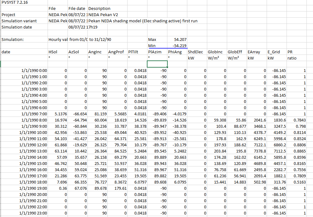
Dear @dtarin, Thanks for sharing this, I decided to take a look at the phi angle limits as per mentioned and as you mentioned, the trackers were performing as mentioned, backtracking within the phi limits. Attached is an image of the backtracking max and min after checking the 8760 as indicated for both situations. The first image is for when I did not specify the pair. The second image is for when I did specify the pair. However, I noticed that in both situations, they both are backtracking but one of them (the first run) has a better shading loss compared to the second run. Why is that? Like the unspecified one will result in better shading losses? Dear @Michele Oliosi, Noted, sure thing, I have sent an email to the email address specified with the same title as this post. Attached are the project file and the PVC export file including the CSV file for the terrain. Thank you.
-
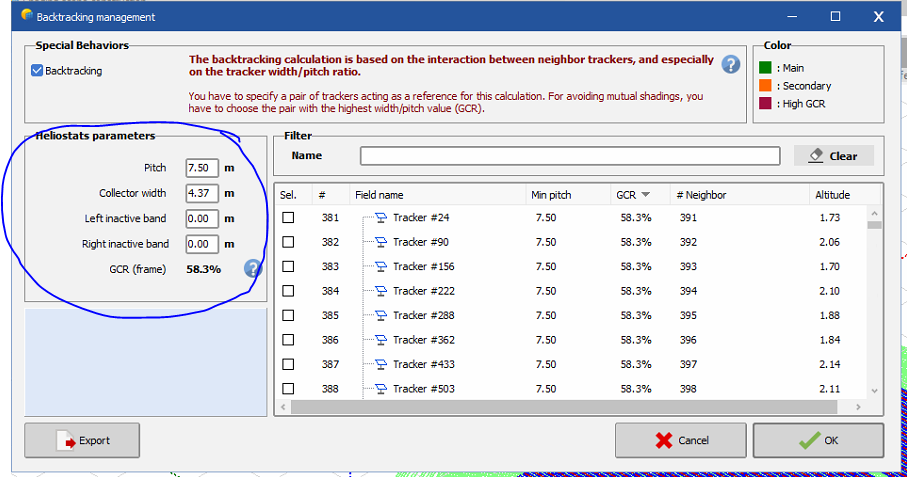
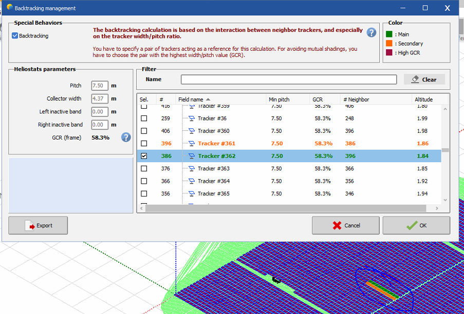
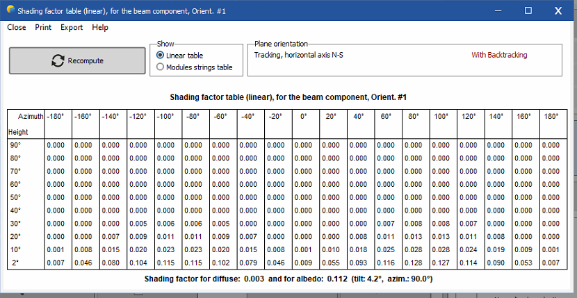
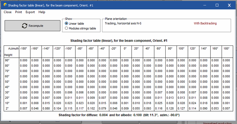
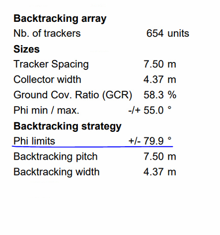
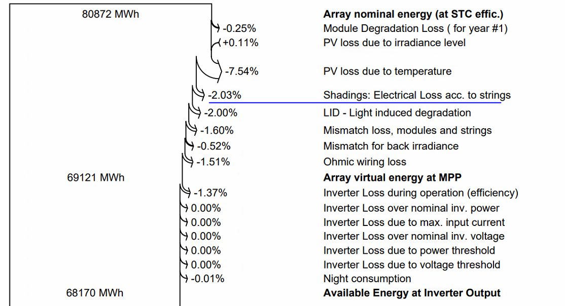
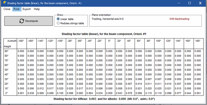
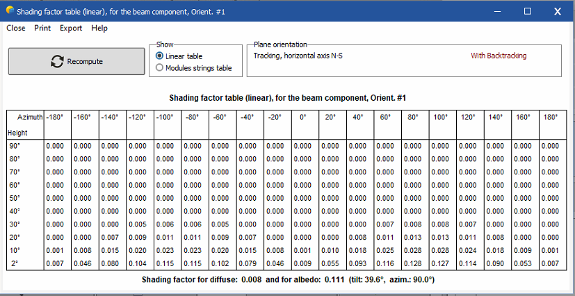
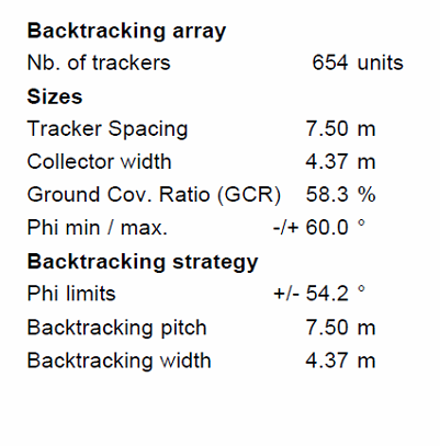
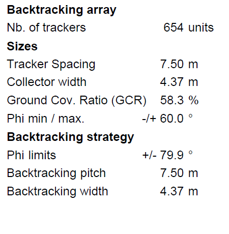
Hi @dtarin, At the time of this post, what I did was doing a generic one by not choosing any same trackers in both instances and instead just doing a generic one as shown here: The results are as the post made, on the first run (Variant VC1) and on the first re-run (Variant VC2), I ended up with very different shading tables and resulting losses are different. Now as of this post, I have tried to choose a 'random' tracker set Number 361 & 362 for both instances: The following are the two shading tables obtained for the two variants: (1st one is VC1, 2nd one is VC2) Both have different tilts and azimuths even though they are the exact same shading model and exact same tables chosen. Moreover, now, for both variants, I am facing the issue that the backtracking is giving +/- 79.9 degrees even though it should have limited the Phi limits. For reference, the project land is pretty flat with minimal undulations. According to PVSyst unlimited horizontal trackers, the phi angle limit should be +/-54.2. However, now, in both variants, I am getting equal electrical shading loss of 2.03% What is going on? Can someone please explain? Cheers.
-
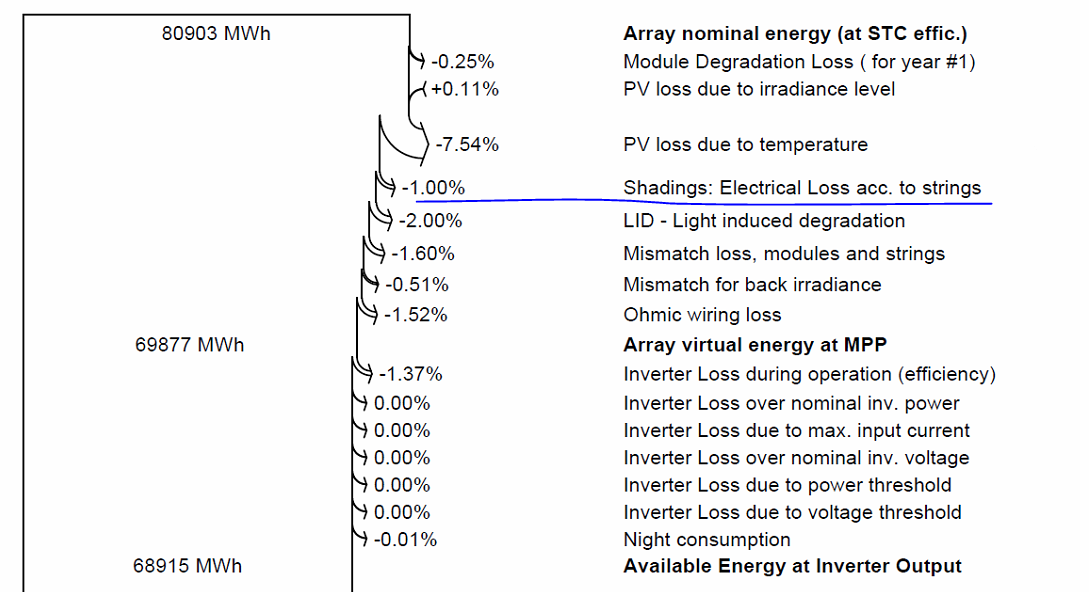
Dear PVSyst Team, I have encountered a situation whereby when importing a tracker array shading model .PVC file into PVSyst and running the first shading table analysis, I am able to obtain one type of shading table as seen in the first image below. The second image shows the shading table for the same exact shading model but a re-compute of the shading table after entering the shading model and exiting without doing any changes and when prompted by PVSyst to recompute, we just clicked yes. The shadings are now different compared to the first run. Moreover, I noticed that this results in the Phi Limits of the backtracking strategy to go haywire. In the first run, the limits seem to conform with what is expected, +/- 54.2 degrees. However, after the re-compute, the limits now go to +/- 79.9 degrees. (3rd and 4th image) Why is that? This causes the electrical shading loss in the loss diagram to double compared to the original first run (as seen in the 5th and 6th images respectively). However, sometimes, after the re-run, we would still end up having the limit angle be completely fine (i.e., it does not go to +/-79.9 degrees but instead, our electrical shading loss remains at 2.03%. Why is that? Looking forward to hearing from you guys soon. Thanks.