
Linda Thoren
-
Posts
355 -
Joined
-
Last visited
Everything posted by Linda Thoren
-
 Hello, Indeed you can make a second variant facing south and compare the results. Your simulation seems reasonable based on the information you have provided, though I of course cannot guarantee that it is all correct. Don't hesitate if you have further questions
 -
Hello, Yes indeed you can do this by activating the "Use multi-MPPT feature" and create multiple sub-arrays. In the right in the system window you have a list of your sub-arrays. For instance, you can assigning 1 MPPT input to the first sub-array with 2 strings and 16 panels in series, and a second sub-array with 1 MPPT and 2 strings with 15 panels in series. In the following Youtube tutorial you have additional information of how to use the Multi-MPPT and Power sharing feature: Kind regards
-
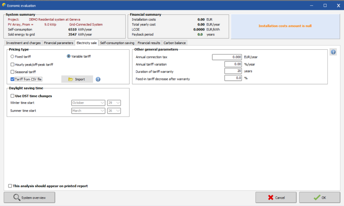
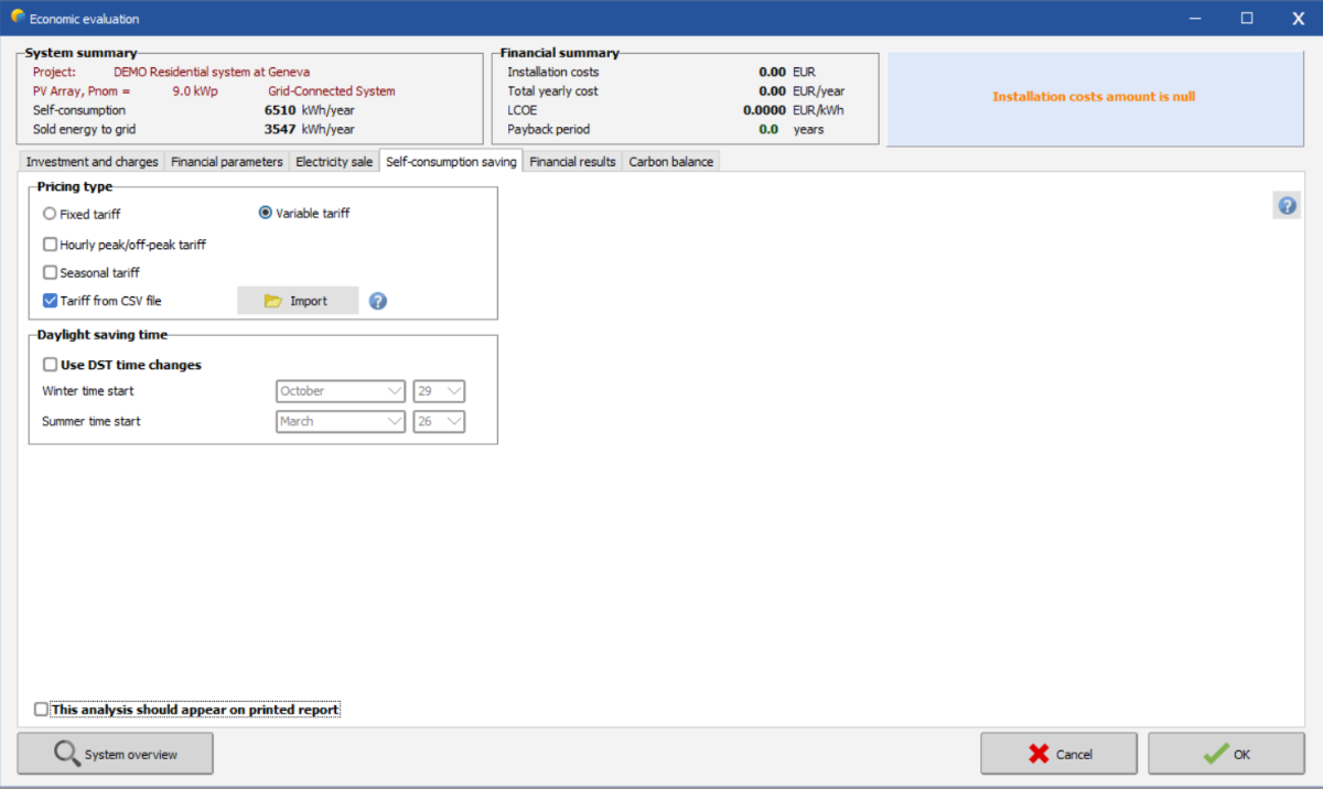
If you have self consumption you can in the economic evaluation calculate the electricity sale as well as the self-consumption saving, see the two print screens below, where the first one correspond to the electricity sale (feed in tariff price) and the second, the price for the consumer to buy from the grid and thus an estimation of how much money is saved by avoid buying energy from the grid but self consume energy from the PVsystem. These can be in hourly values is you import a CSV file. In the following youtube tutorial, you have more information about how to use the Economic Evaluation in PVsyst (though this example is without self-consumption):

-
We have a new video tutorial concerning the multi-MPPT and Power sharing feature, further explaining how to define your system.
-
Dear Leonidas, Sub-hourly simulations are under development, but in the current version of PVsyst the simulation will be done in hourly time-steps. For the self-consumption profile, you can import a CSV file with sub-hourly values. In the economic evaluation you can import a CSV file with hourly time-steps for each hour of the year. In the following PVsyst help page you find more information about the custom feed-in tariffs: https://www.pvsyst.com/help/custom_feed-in_tariff.htm PVsyst will simulate the values you as a user put in, thus it is up to you to define the system that best correspond to your requirement. The input values suggested by PVsyst should be considered as suggestion and not as an optimization or most suitable solution.
-
Indeed the values for the sky diffuse and beam effective on the rear side are rather high. Other than the inclination of the panels, the pitch between the rows and the height above ground will have an impact the bifacial gain. In the analysis tool in the bifacial system definition window, you can evaluate the effect of changing these values as well as generate various graphs to better understand the impact of these parameters. See the youtube tutorial of how to use this tool in the link below:
-
How can I adjust or control the Inverter Loss over nominal inv. power ?
Linda Thoren replied to Abeer's topic in Simulations
To better understand the different losses in an inverter, please read: https://www.pvsyst.com/help/inverter_operating_limits.htm Large Inverter Losses over nominal inv. power could appears in the case if for instance the number of strings are not a multiple of the number of MPPT inputs or if the power sharing is not activated (with a green "active" light). Please see our tutorial of how to use the multiple MPPT and power sharing in the following link: Kind regards -
Hello Allison, When using the multiple MPPT feature, it is important that the numbers of strings is a multiple of the numbers of MPPT inputs, or PVsyst cannot evenly distribute the strings over the MPPTs and you risk increased inverter loss over nominal inverter power. For instance, 46 strings over 18 MPPTs results in 2,5 strings per MPPT. In general, if you have multiple inverters with the same configuration, the number of strings and MPPTs can be multiplied with the number of inverters and be assigned to the same configuration in the Power sharing window. If you think this is not the case, you should define several configurations in Power sharing window, thus also additional sub-arrays. The following youtube tutorial show additional examples of how to use the Multi-MPPT and Power Sharing Kind regards
-
Dear Reza, By "position of the modules", do you mean the location of the installation? The simulation output is based on metrological data that will differs significantly depending on the location. Thus it is not the location per se that is necessary but hourly values of the position of the sun, the irradiance, temperature etc. If you refer to how the tables a placed compare to each other, this can be done in the Near shading and the scene can be saved and exported an image. Kind regards
-
Hello, The global incident in collector plane is the result of the transposition of the irradiance from horizontal to the plane of the array. A collector plane with 90 degrees tilt will receive less irradiance compared to a the horizontal and thus a negative value. Kind regards
-
How to Combine Two Different Thermal Constants in a Single Simulation
Linda Thoren replied to Eduardo.lopez's topic in How-to
Dear Eduardo Lopez, Thank you for your question and for outlining your specific use case. Currently, it is not possible to define different thermal constants within a single simulation, this might be something we can develop in the future. Possible work arounds would be to make a weighted average or divide the project, simulating one variant for each Uc value. Kind regards -
How to select different number of module in 2 arrays
Linda Thoren replied to Tia's topic in Problems / Bugs
Dear Tia, To configurate one string with 5 modules in series and a second with 6 modules in series, you should define 2 sub-arrays (see a list of your sub-arrays to the right in the system window). You can copy your first sub-array, modify the number of MPPT inputs, modules in series and in strings and activate the Power sharing feature, to share the power of the two sub-arrays within the same inverter. We have a youtube tutorial on this subject that further explains how to configure the sub-arrays, the use of the MPPT feature and the Power sharing: You can also fins more examples on the PVsyst help page: https://www.pvsyst.com/help/multi_mppt_use.htm https://www.pvsyst.com/help/multi-mppt_more-examples.htm Kind regards -
How to simulate PVSYST for one day in hourly values?
Linda Thoren replied to hritik's topic in Meteo data
Hello, In the Advanced Simulation window (the button right under Run Simulation) you can precise which dates you want to simulate and by creating a output file, you have the possibility to create a .csv file with hourly, daily or monthly time steps for any simulation variables that are relevant for your project. Kind regards -
Hi! Thank you for your input and concrete example. In PVsyst, peak shaving has primarily been developed as a strategy to manage scenarios with grid limitations by shifting the production peak, rather than as an economic strategy for discharging at peak prices or peak electricity consumption. Further development of storage strategies is planned for next year. Kind regards
-
Hello, The Pnom ratio, also known as the DC-AC ratio, refers to the ratio of the nominal DC power output of a solar panel array to the nominal AC power capacity of the inverter, indicating how much DC capacity is installed relative to the inverter's AC capacity. Thus, the Pnom ratio changes if you adjust the number of panels installed or the capacity of the inverter. Kind regards
-
Hello, In the following youtube tutorial you find the information of how to define a self-consumption profile in a grid-connected system: Kind regards
-
Yes it is possible to import a load profile through the self consumption window. For the importing of hourly or sub-hourly parameters in PVsyst, you must use the following standard format: -Text file (CSV format with commas or semicolons). -All lines beginning with the hash symbol '#' are assumed to be comments, and will be ignored. -Blank lines are ignored. -The first line that does not start with #, holds the column titles. The first two columns should be "Date", and "P Load", further columns are ignored. -The following line contains the units of the data in the columns. The date should have no units, the units for the load can be power ([W], [kW] or [MW]) or energy ([Wh], [kWh] or [MWh]). -Then there follow the lines with the values, one line per data entry. -The date and time in the first column can be given either in European format (DD/MM/YY hh:mm) or in US format (MM/DD/YY hh:mm). -The file should contain all hours of a generic year (from 01/01 at 00:00 up to 31/12 at 23:00). Only day and month will be retained, the year will be ignored. -These dates/hours do not need to be related to the dates of your input meteo file: they are for each hour of a generic year. Please also see our youtube tutorial of how to define a self consumption profile in a grid connected system: Kind regards
-
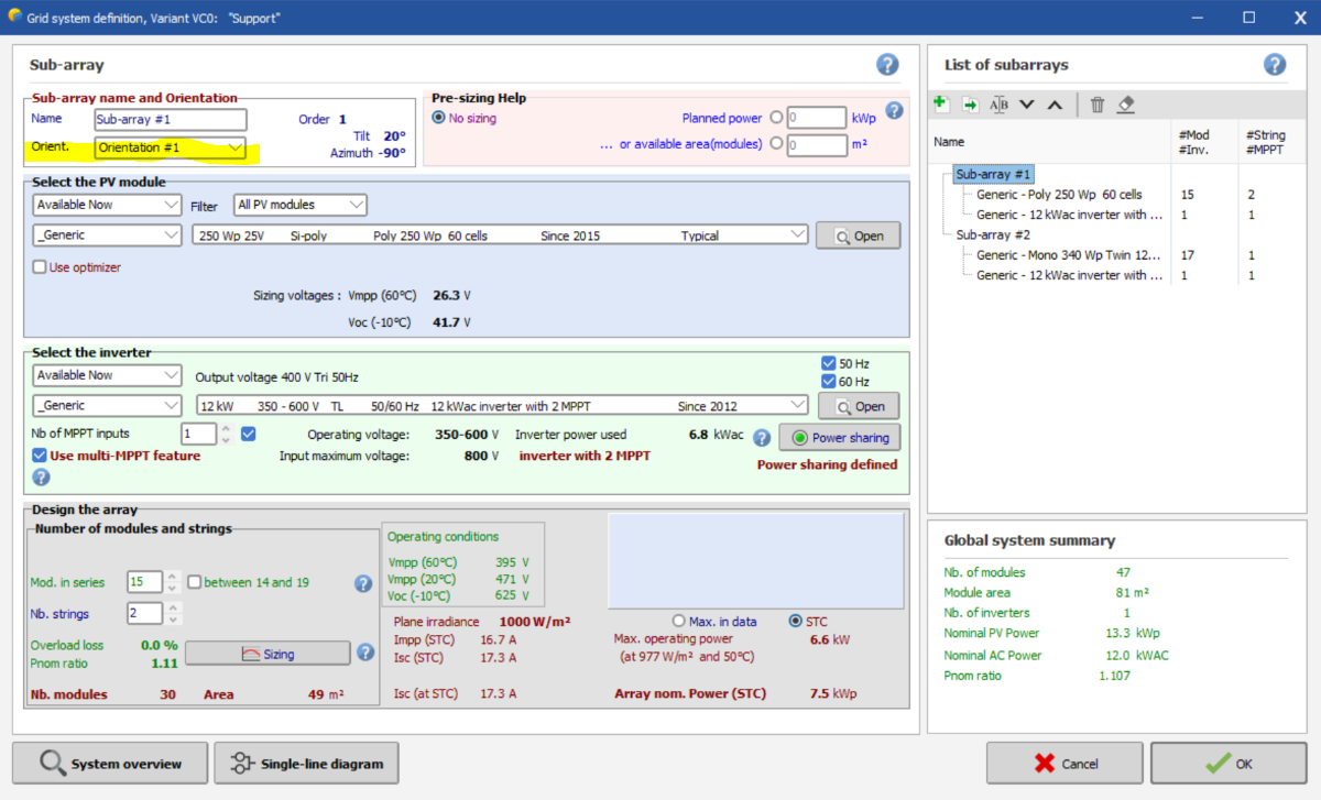
Hello, First you define your different orientations using the field type multiple orientations in the Orientation window. In the system window you can create multiple subarrays (see the List of subarrays to the right) and assign each subarray to an orientation (see the list of orientation that you have defined previously, in the Sub-array name and Orientating angle, orientation highlighted in the print screen below). If your inverter has multiple MPPTs input, you can activate the Use multi-MPPT feature and assign a number of MPPT inputs to each sub-array and use the Power sharing feature for sharing of Nominal Power between MPPT inputs of a same inverter. You can find more detailed explanations of the MPPT feature and Power sharing in the following help pages: https://www.pvsyst.com/help/multi_mppt_use.htm https://www.pvsyst.com/help/powersharing.htm https://www.pvsyst.com/help/multi-mppt_more-examples.htm Kind regards
-
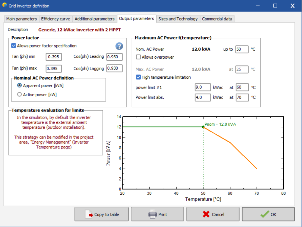
You can see and modify the parameters for your components either from the databases tab in the first PVsyst window, or by clicking "Open" next to the chosen component in the System window in your variant. In the "Output parameters" in the grid inverter definition (in PVsyst this file is called an OND file), you find the parameters linked to the Power factor, see print screen below. By ticking the option Allow power factor specification, the limitation in the Energy management tab will disappear. In the following youtube tutorial you have further information about how the inverter is defined in the PVsyst database: Kind regards
-
More than 8 orientation, and cause error after imported 3d scene into pvsyst
Linda Thoren replied to garf's topic in How-to
Hello, The method suggested above is to increase the tolerance set as default to 1° to a higher value, allowing to group various (but similar) tilts together. Then you should define the system configuration with different sub-arrays for each orientation in the System window. It is indeed possible to have different orientation of the same inverter, though a string cannot be split over two orientations in PVsyst. Don't hesitate to contact us again if you have further questions, either posting in the forum or sending an email to support@pvsyst.com Kind regards -
If the strings have the same lengths, it is sufficient to just untick the Use multi-MPPT feature and define the total number of strings to the inverter. If the strings have different lengths indeed you you will have this constraint in the current version that you can not have empty MPPT inputs. To get around the constraints in PVsyst, you could modify the OND file to 4 MPPTs instead of 6, though by default, PVsyst assumes that an inverter with e.g. 2 MPPT inputs behaves as 2 identical inverters of half the power. You thus might have to adjust other parameters too to correspond to the use-case you are referring too. In the following help page you find more information of how PVsyst defines multi_MPPT inverters: https://www.pvsyst.com/help/multi_mppt_use.htm
-
Hello, Defining a bifacial system with a 3D scene comes with certain constraints, ensuring the regularity of the arrangements of tables for the bifacial 2D model computation. You can read more about the 2D model conditions in the following help page: https://www.pvsyst.com/help/bifacial-conditions.htm The threshold for regular pitch can be modified in the advanced parameters, by changing the value "Pitch RMS limit for bifacial 2D models" Kind regards
-
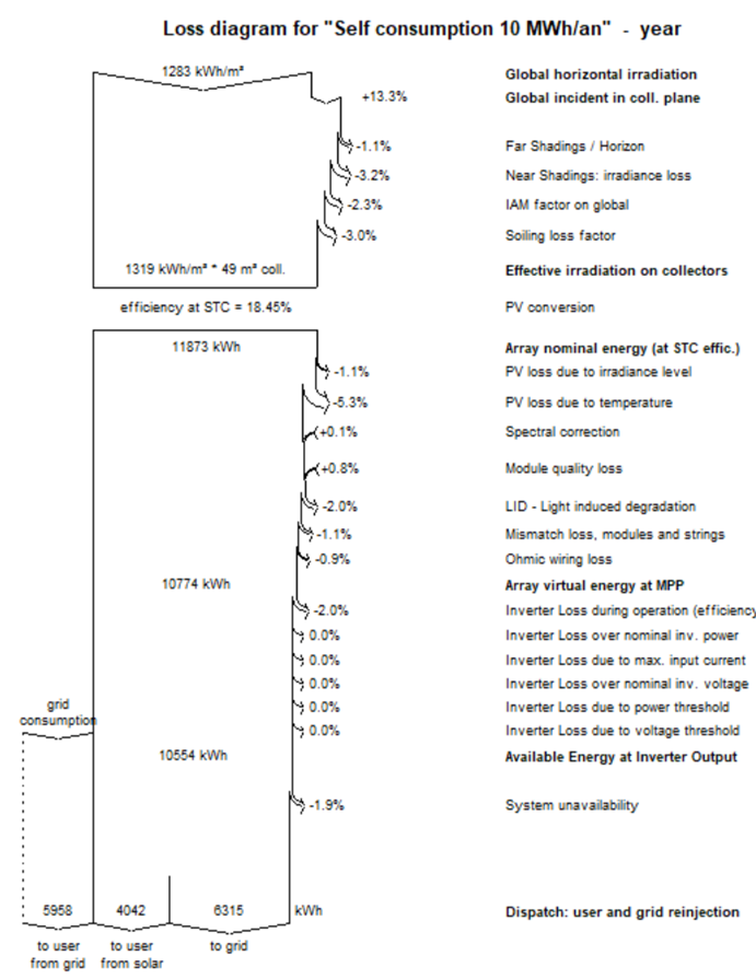
Hello, In PVsyst it is possible to define an hourly self-consumption profile and in the economic evaluation you can also define precise tariffs for electricity sale as well as calculating the gain from self-consuming compared to grid consumption. I link 2 video tutorials below. A large enough system will fulfill the energy need by day, as well as injecting the excess energy into the grid. For example, below you see the loss diagram for the DEMO Residential system at Geneva variant VC4 : The result is divided in to user from grid, to user from solar and to grid. You can also include a battery storage solution to increase the self-consumption, though it is not yet possible to inject energy stored in the batteries to the grid (unless you use the peak shaving strategy, that can not be combined with a self-consumption profile) In the Advanced Simulation window, you can then create an Output file with all the relevant parameters for your project in Daily or Hourly timesteps. I hope this helps to get started with your Net billing project, Kind regards
-
Diff. Orientations in the same string and same MPPT input
Linda Thoren replied to Umut's topic in How-to
Hello, It is not possible to have multiple orientations on the same string. If you have two or more strings, it is possible to put two orientations on the same MPPT input by using the Mix orientation 1 and 2 option (you might have to change the order of the orientation since it in this version of PVsyst is only possible to mix orientation 1 and 2). Kind regards -
You have chosen a 7.0 kW inverter, and panels with a nominal power of 5.0kW, thus the inverter is a bit oversized. With an orange warning you can still run the simulation. Please look at the following video tutorial for more information about the sizing: Kind regards