
Linda Thoren
-
Posts
69 -
Joined
-
Last visited
Everything posted by Linda Thoren
-

Daily extra-terrestrial irradiation on horizontal plane (H0)
Linda Thoren replied to khaoula.rahrah's topic in How-to
Hello, In the Advanced Simulation, you can create an Output File with hourly or daily values for a large number of variables, for example Global horizontal irradiation, Sun height, Sun azimuth, Global corrected for horizon/far shadings. Kind regards -
Hello, The inverter clipping losses, the Inverter loss over nominal power, is to large extent due to the sizing and configuration of your system. If you have higher clipping losses than expected, it could be due to the the definition of the multi-MPPT inputs. Please read the following help pages on the subject: https://www.pvsyst.com/help/powersharing.htm https://www.pvsyst.com/help/multi-mppt_more-examples.htm It could also be temperature derating, at high temperatures inverters often have a lower nominal power. You can see the temperature evaluation of the inverter in the Output parameters in the .OND file.
-
Hello, To our knowledge there is no bug in the multi-MPPT features. Large Inverter Losses over nominal inv. power could appears in the case if for instance the number of strings are not a multiple of the number of MPPT inputs or if the power sharing is not activated (with a green "active" light). Please read more about the multiple MPPT and power sharing in the following help pages: https://www.pvsyst.com/help/powersharing.htm https://www.pvsyst.com/help/multi-mppt_more-examples.htm If you still have difficulties, please send your project as zip file to support@pvsyst.com and we can have a closer look at it. Kind regards
-
Hello, Far shadings from mountains can be accounted for in the Horizon window. This tool is aimed to treat shadings of objects sufficiently far, as we can consider they act on the PV field in a global way: at a given instant, the sun is or is not visible on the field. The following two help pages further describe the Horizon profile and how to import the horizon from the web, based on the the systems exact location https://www.pvsyst.com/help/horizon.htm https://www.pvsyst.com/help/horizon_import.htm I hope this answers your questions, Kind regards
-
Hello, You have 2 orientation defined but only one string per inverter, that is why you cannot mix the orientations. So if you want to use the Mixed orientation option, increase the number of strings, click OK and then go back to system again and this option will be activated. You cannot mix the orientation in an sub-array that has only one string. If you define a sub-array with 2 strings and mix the orientations, you will have one string in each orientation (and you can erase the second sub-array). In your current system you have defined one inverter per sub-array. An other alternative is to activate the Use multi-MPPT feature and define 1 MPPT per subarray and then activate the power-sharing. Like this you can define one sub-array in each orientation but using only one inverter. Kind regards
-
Hello, In your system, you have defined only one string. When defining orientations only entire strings are considered. Thus the Mixed orientation option in not available unless you have at least 2 strings. If you increase the number of strings, save and go back to System, the Mixed orientation option will be available. If you indeed mean to have only one string, you should instead make an average of the two orientations. Kind regards
-
Good day! Normally the Mixed orientation option is there as in the previous versions. I cannot manage to reproduce the situation you are in where indeed two orientations are defined without the third option of Mixing them. Can you please send your project as a zip file to support@pvsyst.com and we can have a closer look at it. Kind regards
-
Dear Stephen, Thank you for your question. The peak shaving strategy cannot be combined with the self-consumption strategy, this might be something we will develop in the future but it is not yet on the road map. For the peak shaving strategy you will define a grid limitation and energy that would be curtailed because of the limitation can instead be stored in a battery pack and injected at a different time. In the self consumption strategy you will define your load profile and simulate how much of the production you can self-consume. With a battery storage solution you can increase the self-consumption by storing the energy produced during the day to fulfill the energy need at night, thus the energy from the battery storage will not be injected to the grid but is aimed at fulfilling the users need. With the self consumption strategy you can however still impose a grid limitation through the energy management tab. In the following link you find a playlist with our youtube tutorials of how to define a self consumption profile and how to use the different storage strategies
-
How to generate hourly data with probabilty different than P50
Linda Thoren replied to Panagiota's topic in How-to
Hello, The P50-P90 statistical estimations are based on yearly values and defining P75 for hourly values would give erratic results, thus this is not possible in PVsyst. You can find more information about the p50-p90 estimation in the following help page: https://www.pvsyst.com/help/p50_p90evaluations.htm Kind regards -
The inverter efficiency depend on a certain extent on the DC power. In the .OND file, in the Efficiency curve tab you can see the relation between the inverter efficiency and the Power in the DC circuit. The efficiency is then calculated in hourly time steps in the simulation and monthly averages of the total production is shown in the report. The PR is also calculated in hourly timesteps and monthly and yearly averages are shown in the report.
-
Generic Values (MV transformer/ Transformer from Data sheet)
Linda Thoren replied to Rajesh saha's topic in PV Components
Dear Rajesh saha, Your understanding is correct! At the moment the temperature and the losses due to high temperatures are not being considered at the transformer level, these are parameters we might include in future versions. So if your transformer will operate at 50°C, you should use the values for these conditions. Kind regards -
Near shading drawing in standalone system
Linda Thoren replied to n.ragavander's topic in Shadings and tracking
Hello, In the current version of PVsyst it is not possible to use multiple orientations in a standalone project, this will be possible in the coming version 8. For now you can simulate your project as a grid connected system with multiple orientation and in the storage parameters, not allow injection to the grid. In case your result includes energy from the grid to fulfill the users need, that should be considered equivalent to missing energy in a standalone project. Kind regards -
Hello, The yearly production from your system is much larger than the consumption. If you do not allow injection to the grid there will be a lot of losses even with battery storage. In your calculation you say you need a storage system of 20kWh but in your picture you have defined a storage of almost 20000 kWh. With such a large storage and low charging and discharging power PVsyst gives you this error message. You can also see in the system information for instance that you have defined your system so that discharging under maximum load will take 20359.5 hours.
-
Hello Mohamed Abdelkader, Thank you for your question. It is not directly clear why this number change, it is likely linked to the Global capacity (C10) used to calculate the stored energy at 80% DOD in the definition of the storage pack and that some definition or values might be different when this value is estimated for the characteristics in the report. The possible difference in capacity depend on for instance the discharge rate, see the graph below. Thank you for highlighting this, we will look into it.

-
Hello, PVsyst does not have any default numbers or recommendations and regarding the temperature shift. The temperature shift can depend on various factors such as characteristics of the inverter, your installation method and site.
-
Dear Solaranger, Indeed the values here looks a bit strange. Please send your project file to support@pvsyst.com and we can have a closer look at it. Kind regards
-
Dear Joaquina, The warning message indicates that the Max. charging power is too high and that you should consider increasing the battery capacity or reduce the charging power (by reducing the charging power you are increasing the c-rate). This is a limit that you can change in the advanced parameters. If you have a Lead-acid storage the minimum charging/discharging rate is set to 2.5 hours. you find these parameters in the category Verification on Grid systems (#815 and #816 for Lead-acid Storage) Kind regards
-
Dear Madela, The Global incident in collector plane (GlobInc) measures the solar radiation received on a surface that is inclined or tilted in [kWh/m2] (compared to the Global horizontal irradiation (GlobHor) that measures the total solar radiation received on a horizontal surface, such as the ground). The GlobInc is the result of the transposition from the GlobHor from the meteo data. Thus changing the tilt or the azimuth will change the GlobInc, but it will not be affected by the size of your system given that the value is normalized (given in energy per unit area) In the Orientation window, you can see a quick optimization of which plane tilt and azimuth that results in the highest Global on collector plane at your site. Kind regards
-
Hi Auxi Madero, Very true! In the Pan file, in the Additional Data, Degradation you can change the Global degradation factor on Pmpp. Normally this value is indicated per year in the panels data sheet, and should for 10 years be a value of something in the order of magnitude of 3.8%. By modifying the PAN file and saving it with a new name, you can create your project with the two variants of panels. In the Detailed losses window, in the Module quality - LID - Mismatch tab you can also increase the Module mismatch losses for the sub-arrays with the degraded modules. Kind regards
-
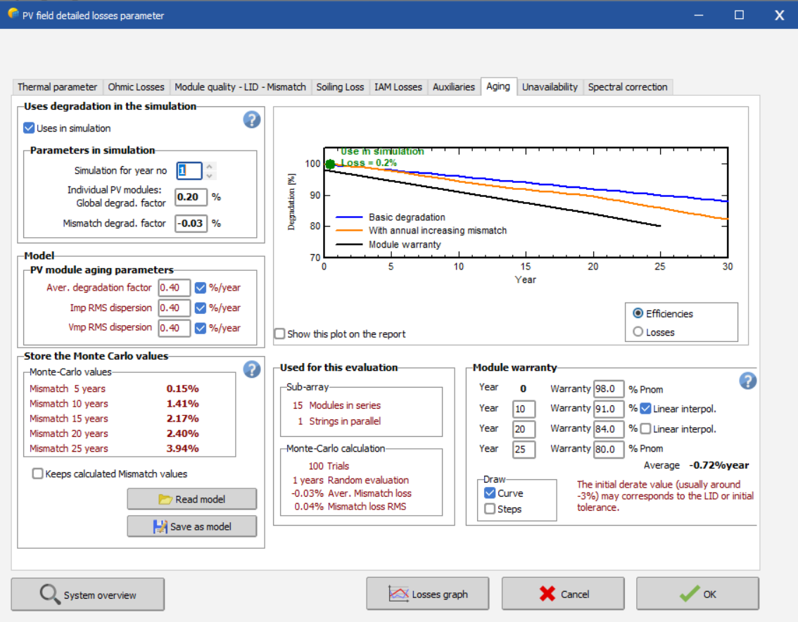
Dear Main AlBataineh, I assume you are using the aging tool in the advanced simulation. If the production year 1 in the results in the aging tool is slightly lower than in the results summery, it could be because the aging has not been defined in the detailed losses. If you in the detailed losses window, in the Aging tab have not ticked the box "Uses in simulation" (see screen shot below), the simulation will not take the aging into account. If you in the detailed losses window under the aging tab have defined the aging parameters, the produced energy that defined year, should correspond to the value that same year in the aging tool in the advanced simulation. Kind regards
-
Dear Auxi Madero, In detailed losses, in the Aging tab you can simulate the degradation of your system after 10 years, though only for your entire system. To get around this you can divide your project and run one simulation for the already existing system and a second for the new additional part. Kind regards
-
Dear hvf, The grid limitation is reflects a scenario where the grid manager impose a limit to the injected power to the grid. If your system at certain moment produce higher then this limit, it will be managed by the inverter as a clipping loss. There is a help page here explaining this further: https://www.pvsyst.com/help/grid_power_limitation.htm The power factor is the ratio between active and apparent power, i.e. Cos(phi) and does not limit the power to the grid at a certain threshold. The active power is the power obtained along one sinus period, when we integrate the product of the instantaneous Voltage by the Instantaneous Current at each time step. This results in a multiplication by the cosine of the phase shift: Pactive = Ueff * Ieff * Cos(phi) expressed in [kW]. The reactive power is the vectorial difference of these contributions: Preactive = Ueff * Ieff * Sin(phi) expressed in [kVAr]. Following help page explain the Power factor further: https://www.pvsyst.com/help/power_factor.htm Indeed, if the Nominal AC Power is defined in Apparent power in the inverter file, the two variants should give similar results. To assist you further please provide us with the loss diagrams for the two variants, or send your project to support@pvsyst.com Kind regards
-
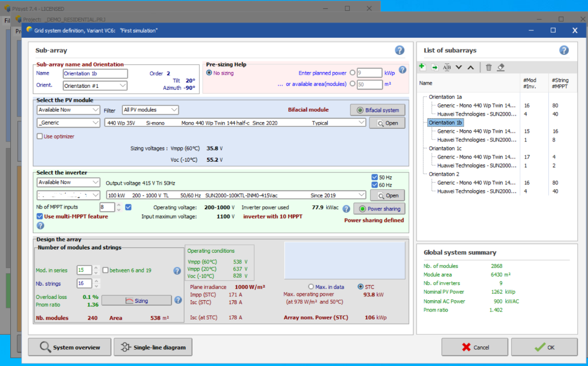
Hello Sascha, By using the mixed orientation option, all the strings are the same lengths and by increasing the numbers of strings, you then increase with 16 panels every time. You have more liberty if you define sub-arrays, you then assign each sub-array to an orientation/inverter/MPPT. In the Sub-array name and Orientation dialog you can define a name of your sub-array and the orientation, in the generic example below I have 2 orientations, 3 subarrays in the first orientation and 1 subarray in the second orientation, see the list of subarrays to the right. You can create a new subarray, or copy a subarray by using the first two icons under the list of subarrays. I also activate the use multi-MPPT feature for this example and I activate the power sharing. Using these features I have defines a global system with 2868 modules and 9 inverters (1588 panels and 5 inverter in orientation 1 and 1280 panels and 4 inverter in orientation 2). I hope this example helps you to define your system. If not please send your project to support@pvsyst.com Kind regards
-
Dear Sascha N. By creating subarrays you can define different amount of panels per string, different amount of strings per MPPT, orientation etc. This gives you a large liberty to define exactly the amount of modules required. You find the list of subarrays to the right in the system window. I hope this helps, if you wish for more precise assistance, please provide us with more information of your system. Kind regards
-
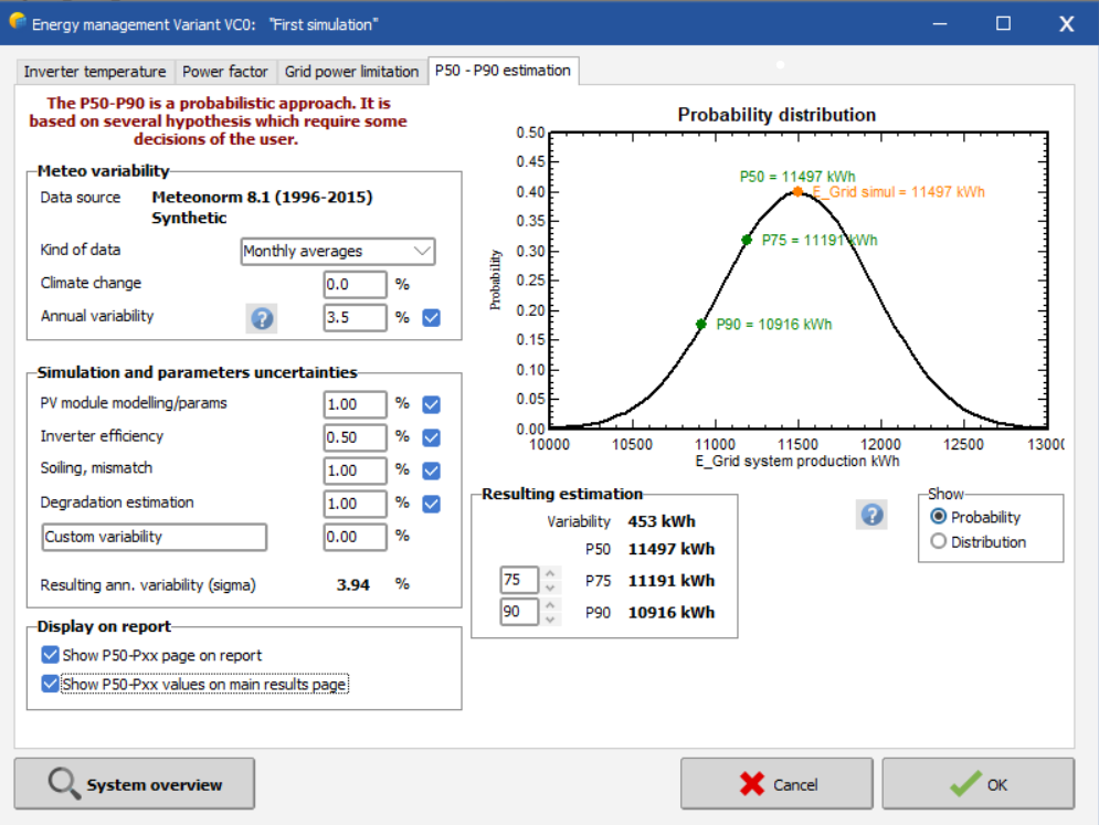
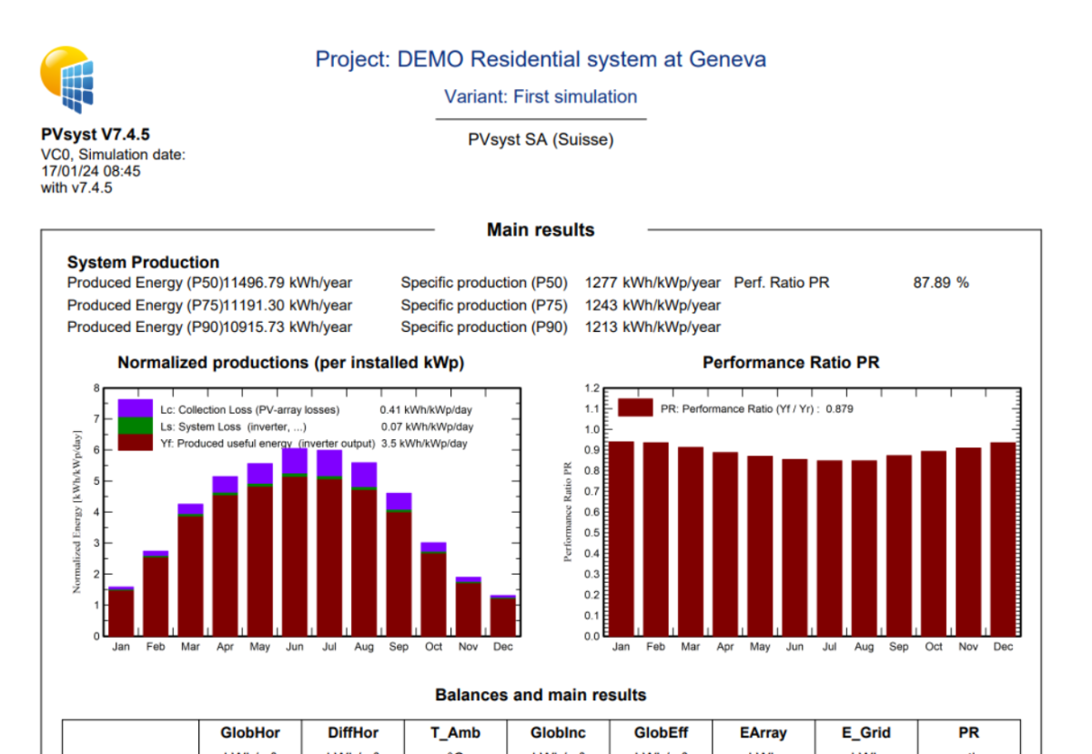
Hi, Make sure you have ticked the alternative "Show P50-Pxx values on main results page" in the "Display on report" box in the P50 P90 window, see below. By generating a report, your main result will include also the specific production for the defined Pxx. See below the report of the DEMO Residential system at Geneva. Kind regards