
Michele Oliosi
-
Posts
811 -
Joined
-
Last visited
Everything posted by Michele Oliosi
-
On the main window, try going to File > Reload databases. As a second point, please check that coordinates do match closely. Let us know if either helps.
-

Pr different in report and hourly data file
Michele Oliosi replied to IgLoo's topic in Problems / Bugs
Can you explain your calculation for the monthly average PR ? -
how to set the string configuration in this case
Michele Oliosi replied to garf's topic in Simulations
At the moment you cannot set different strings on the same MPPT within PVsyst. However you could modify the inverter and add an extra MPPT. As long as you are careful with the "power sharing" configuration, it can be a good representation of your system. -
Polygonal field edition: module spacing and padding edition
Michele Oliosi replied to sunway's topic in Problems / Bugs
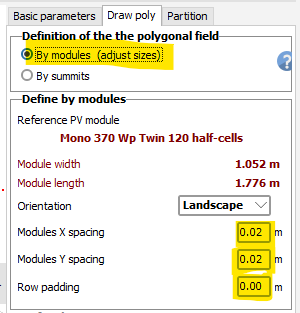
At the moment the workaround is to switch directly to "by modules". Adjust the spacing. Go back to "by summits" and redesign the polygon. I have submitted a ticket to improve the functionality at some point in the future. -
Polygonal field edition: module spacing and padding edition
Michele Oliosi replied to sunway's topic in Problems / Bugs
I see, I will check whether we can create a similar functionality in the newer PVsyst as well. -
Another point that may be at play: the module parameters have to be recomputed to be able to apply the degradation. If you are using a module that doesn't have standard one-diode parameters to begin with, once the aging is applied, they may change due to the recomputation of these parameters.
-
Yes it is the same issue with or without backtracking.
-
How to download the month wise expected module temperature in deg c
Michele Oliosi replied to winothkanna's topic in How-to
As far as I know, in the context of PVsyst they are the same (cell and module temperature). I will add a note in the help. -
Polygonal field edition: module spacing and padding edition
Michele Oliosi replied to sunway's topic in Problems / Bugs
If you click on "by modules (adjust sizes)" instead of "by summits" you should be able to change the module spacings.
-
Recently released v7.2.21 should fix the bug.
-
Recently released v7.2.21 should fix the bug.
-
Orientation > Tracking, horizontal axis N-S
Michele Oliosi replied to julmou's topic in Shadings and tracking
Thank you for the feedback. This is a known bug for the drawing only and its correction is in our roadmap. It does not affect the simulation in any way. -
Polygonal field edition: module spacing and padding edition
Michele Oliosi replied to sunway's topic in Problems / Bugs
Hi, Please provide your question in english if possible. The language of the forum posts is in english (see forum rules). You can send us your questions at support@pvsyst.com you can turn on these settings by clicking on "by modules (adjust sizes)"
-
@laurahin You are right, only one pitch is being used atm: the average pitch.
-
Patch 7.2.20 has introduced an error affecting the partitioning into rectangle strings of tracker objects. The partitioning, either via the object management window or the individual objects edition windows, will not respond correctly to the inputs such as "number of partitions in X", and will not draw the partitioning correctly either. As a consequence, the shading animation and calculation of the electrical shading factor table will give erroneous results. Typically this yields 0% electrical shadings in the yearly results or losses diagram. This bug affects trackers only. For previously created projects, the trigger for the bug is opening the 3D scene and the tracker object definition, which will break the partitioning. We know of no workaround at the moment, but are working to provide a patch very quickly for this error. It should be published within this week. In the meantime you can also work in the previous version 7.2.19, while waiting for the patch. For that you need to uninstall and reinstall PVsyst. This has no averse effect on the licence, which stays active through the process. Here is the page with all previous versions: https://www.pvsyst.com/previous-versions/ Related post 1 : https://forum.pvsyst.com/topic/2935-partition-function-does-not-work-for-tracker-imported-from-pv-case-after-last-updated-720
-
Optimizing tilt adjustment monthly
Michele Oliosi replied to babikhoja's topic in Shadings and tracking
Hi, At the moment in PVsyst we only have a tool to check multiple orientations within the clear day scenario: For anything other than clear day (taking into account a specific weather file), you should use the optimisation tool and run it while specifying a specific temporal range for the simulation: Note however that that optimum will be true for a specific weather file only !
-
Difficult to say with monthly data only. But the diffuse seems to be quite different, which could explain differences before and after transposition.
-
Tracking ranges (datasheet vs PVsyst input)
Michele Oliosi replied to solarDG1470's topic in Shadings and tracking
Hi in fact PVsyst will compute the angle as follows: 0 = horizontal tables. But the angle is measured using the normal to the plane, so the angle is measured from the vertical axis to the normal to the plane. +-50° cannot be steeper than +-60°. You are probably mentioning this because of the drawing on the right of the orientation window. The green lines and red dot are in fact limits for the handle that you see in the middle with a blue line and a red dot (you can move it around to see the range). That corresponds to the opposite to the plane normal. It's not very intuitive but it is there historically, we will change this at some point. -
We are currently working on the issue (thanks @Angelov for the example files). Basically the partitioning for NS-axis trackers in version 7.2.20 has a bug, that will take place whenever you open a tracker definition window, e.g. to try to modify the partitioning. As far as we know there is no workaround other than reverting to 7.2.19, but a corrective should come out soon (my colleagues already fixed it on our development branch).
-
Well noted, I made a reminder to update the information. Thanks !
-
Thanks for letting us know, indeed we need to fix this bug asap
-
Hi ! Can you send us the PVC file at support@pvsyst.com ? We'll gladly look into the issue. Thanks in advance.
-
Climate change meteo variability in energy management
Michele Oliosi replied to Bilal Shahid's topic in How-to
Hi, The idea is to model upwards or downwards historical trends in terms of PV yield for a specific location. As you probably already understand, these trends depend completely on the location, and may be quite difficult to forecast. However if you are able to estimate this trend, then this tool will let you raise or lower the value used as P50. One simple case is when you are using older weather data. In that case you want to find whether the present weather yields more than past weather. Since it is historical data, you can more easily find documented trends for the specific location under study, either from publications or directly studying time-series data. The second case if forecasting, which of course is more difficult. Nonetheless you may be able to find some climate change forecast scenarios depending on your location. For example in Switzerland, the national centre for climate services provides this kind of information. -
Need advice for complex shading scene
Michele Oliosi replied to Helioworks's topic in Shadings and tracking
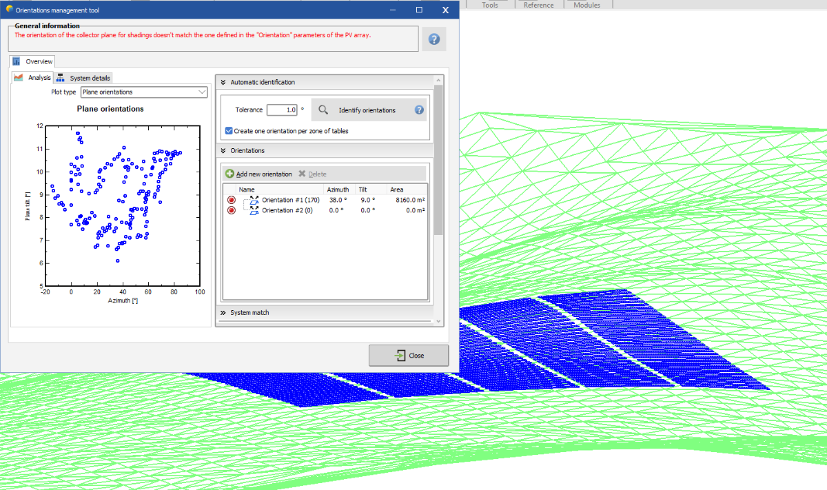
Hi, In the 3D scene, Tools > Orientation management tool, you will find a tool that will help you reduce the number of orientations. There are several ways to proceed, either semi-manually, or by changing the tolerance to identify different orientations. If you double click on an orientation, you can assign tables to it. In the above example all tables have been assigned to orientation #1, so you should first unassign them before assigning them to another orientation group.
-
Two frame axis - backtracking in both directions
Michele Oliosi replied to Falberto76's topic in Shadings and tracking
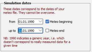
@Falberto76 you can launch the simulation for shorter periods, but the same period for all the batch runs if I recall correctly. You select the option when choosing the simulation dates in the "Advanced simulation" window. Do tell me if that doesn't work.