
Michele Oliosi
-
Posts
814 -
Joined
-
Last visited
Everything posted by Michele Oliosi
-
 Indeed, at the moment this is not possible in PVsyst. We only model the impact of mutual shadings for the backside irradiance modeling.
 -
There is no mistake in your settings. At the moment, the bifacial backside irradiance model is a 2D view factor model, that approximates the situation of the 3D scene. Shading objects are not represented, neither are differences in height of the tables and so on. One partially related point is that the “Height above ground” in the backside irradiance model definition is not retrieved from the 3D scene either. You should therefore enter it manually according to your system specifications.
-
No azimuth parameter in optimisation tool for SAT
Michele Oliosi replied to Vladislav Iliev's topic in Simulations
Hello, Indeed, the optimization tool is quite rudimentary and doesn't include many parameters to vary. You can however change this parameter with the batch mode, which has many more capabilities than the optimization tool and is useful for more advanced comparative studies. -
We will release more information as it comes along. For the moment, I can just say that it should be expected sometime in 2024. Currently, as mentioned on this recent post we are trying to release V8 this year, as early as it is feasible. We would like to add the sub-hourly modeling correction feature in either of V8.0 or V8.1.
-
What I meant is that if you define a single sub-array containing 100 inverters and, 2114 strings: PVsyst will evaluate the average DC:AC ratio for the sub-array, on this window, only to trigger warnings. In this instance, it does not trigger a warning. For the simulation, PVsyst will consider : 86 inverters with 21 strings x 32PV per string; and 14 inverters with 22 strings x 32PV per string. Instead, if you properly define two sub-arrays with 86 inverters with 21 strings x 32PV per string; and 14 inverters with 22 strings x 32PV per string: For the evaluation of warnings, this time each DC:AC ratio is computed, since this is done sub-array per sub-array. One of the sub-arrays triggers a warning. For the simulation, there is no difference: PVsyst will consider 86 inverters with 21 strings x 32PV per string; and 14 inverters with 22 strings x 32PV per string.
-
We have some improvements that will help on our roadmap. In particular, in version 8, it will be possible to define multiple tracker orientations. This will be useful in case there are few distinct slopes (+ small variation, that will be averaged upon).
-
Bifacial modules - Tracking, horizontal axis E-W
Michele Oliosi replied to Virgil Ciolponea's topic in Simulations
Dear Virgil Ciolponea, Are you sure you want to use E-W trackers? This type of tracker is more uncommon. NS-axis trackers (turn towards east in the morning and face west in the evening) are more common. Unfortunately, the bifacial calculation only handles NS-axis SAT at the moment. Even though PVsyst will formally allow turning the N-S axis tracker 90° around, it will not lead to good results, especially in backtracking mode (the backtracking of EW and NS axis trackers are different). If you need a bifacial gain value, I would suggest extrapolating the values using a fixed tilt variant to establish an approximation of the bifacial irradiance gains. -
Reset to automatic determination of the inverter PNom limitation mode
Michele Oliosi replied to laurahin's topic in How-to
Hi Laura, Thanks for the suggestion ! Indeed, at the moment other than tweaking the files, there is no way to reset this. I filed a ticket to find a way to reset the state. -
EW systems orientation from pvcase to pvsyst
Michele Oliosi replied to n.ragavander's topic in How-to
Hi, Unfortunately, in v7 it is impossible to have both trackers and fixed structures in the same variant. You should simulate them separately instead. This limitation will be lifted in v8, to be released sometime in 2024. -
which settings in particular ?
-
Yes, that would be the correct way to proceed. If the irradiance is already reduced by a horizon of some kind, no need to account for it a second time in PVsyst.
-
Batch simulation Engergy output overprediction
Michele Oliosi replied to TKR's topic in Problems / Bugs
In this case, we expect that batch simulation and regular simulation agree. There are however a few reasons for which batch simulation and regular simulation may disagree: The unavailability losses may be randomized again by the batch mode ? Do you have unavailability losses included in your variants ? Aging mismatch losses may be randomized again if they were not “saved as template”. Please check your aging losses. If neither of these are active, please send us an example project and batch parameter file. By the way, you mention 1-20MWh but what is the relative error ? Anything below 0.1% might also be due to rounding errors. -
Indeed, 7.3.X was significantly underestimating the losses in some situations. 7.4.X is much better, although we will make a further adjustment for trackers in version 7.4.6.
-
Hi ! The height above ground is indeed crucial if you are using bifacial modules or large tilt values. For monofacial modules, solely oriented towards the sky, it does not matter too much. Therefore, the height above ground is a parameter in the bifacial model for the backside irradiance. It is available in System, as soon as you choose a bifacial module. The button Bifacial system allows you to parametrize the bifacial modeling.
-
New to Batch, no CSV created plus how to
Michele Oliosi replied to John Dozla's topic in Simulations
The date 1990 is an indicator in PVsyst and not an actual year. It means that the year is generic, i.e., you are using multi-year averages or a TMY. If you import your own time-series data, e.g., via the custom import file, you can choose to use the dates specified in the file. If you then use the MET file created by this procedure, you will be able to choose dates according to your time-series. -
Apart from unlimited orientations, the orientation choices do not allow specifying the distance between trackers. In these cases, the distance between trackers is specified solely by the 3D scene. It is however relatively easy to create an array of trackers in the 3D scene, and the EW pitch i.e., the distance between trackers is one of the parameters.
-
Hi, The axis tilt spread does not impact the simulation results. It just lets you choose what is the maximum tilt difference in your scene. If you don't want to see the error, you can just put a large value in the advanced parameter. Note, however, that the more differences you have in tilt in your scene (independent of the advanced parameter choice), the less the transposition calculation will be precise because of the averaging error.
-
How to adjust varying N/S tilt of multiple trackers
Michele Oliosi replied to Vera's topic in Shadings and tracking
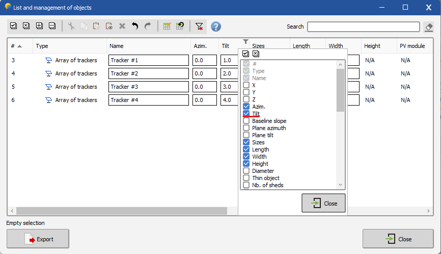
In this case, it is often best to go through the advanced object selection: https://www.pvsyst.com/help/near_shadings_advancedselection.htm If the tilt column is not present, you can right-click on any column header to see the selection of columns:
-
There is no impact of increasing this number. It simply allows simulating situations which are not well modeled by the bifacial backside irradiance model.
-
Please check the following help page: https://www.pvsyst.com/help/bifacial-conditions.htm This is not a bug but the current limitation of the bifacial model. It is possible to extend the modeling to situations with an inhomogeneous pitch, via the advanced parameters described in the help page (increase the threshold pitch RMS deviation value). The simulation will run, however the results may be somewhat inaccurate for the backside irradiance.
-
Hi, This recent publication may be useful to you. https://www.pvsyst.com/wp-content/publications/2023/2023_PVsyst_OneDiodeModel_EUPVSEC.pdf Actually, we fix Rs according to low-light data, i.e., there is no temperature or irradiance dependence in this parameter. Let me know if I misunderstood your question !
-
Decomposition and transposition models
Michele Oliosi replied to dina.christensen.martinsen's topic in Meteo data
Hello, This sounds like a great research. Are you going to publish it? If so, we'd gladly go through it once it's out there. In PVsyst you can always (and it is recommended to do so) import DHI or DNI in addition to GHI. This means that we do not need to rely on DirInt or Erbs for diffuse estimation. Currently, it is also possible to import POA data as part of the custom file import (https://www.pvsyst.com/help/meteo_convdialog.htm). What this does is that it uses Hay for reverse transposition to get both GHI and DHI, and then uses these values for the simulation (as well as the Hay transposition). This means that the POA used in the simulation will be the imported one, however the decomposition in different irradiance components will be according to the Hay model. We could add more decomposition / transposition models if necessary. We will establish this type of developments by first having a thorough look at the literature. I think your research would help us as a first step to assess the need to implement other transposition / decomposition models. -
Indeed, please look here https://www.pvsyst.com/help/output_file.htm you want the variable ShdElec
-
Yes, we differentiate between mismatch caused by shadings (= electrical shading loss, ShdElec) and other types of mismatch (MisLoss), e.g., due to the quality of the modules. If you use “mixed orientations”, i.e., strings that have different orientations connected in parallel, there can also be a mismatch due to that (MixLoss). All these variables are given as hourly values, if you run a simulation with output file https://www.pvsyst.com/help/output_file.htm
-
Why 0°? Southern facing side will have an azimuth of -90° (E) + 42.2° = -47.8°.