-
Posts
792 -
Joined
-
Last visited
Everything posted by Michele Oliosi
-
As was answered many times in the forum, in PVsyst v7 it is not possible to use the bifacial model with multiple orientations. You should simulate the orientations one by one.
-
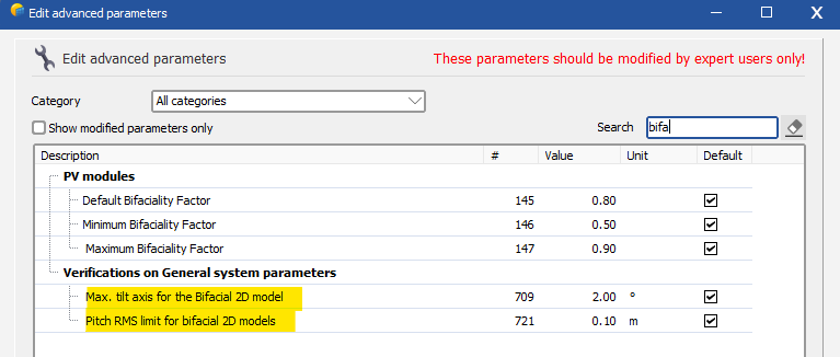
This is a very common question in the forum. Please read the following page carefully: https://www.pvsyst.com/help/bifacial-conditions.htm The error message indicates that the bifacial backside irradiance model, which is a simplified 2D model, is not very representative of the 3D scene for some reason. Also, note that the bifacial model can only work in V7 for a single fixed tilt or SAT orientation, in regularly arranged rows. For fixed tilt / SAT, the error will appear if the pitch is not regular in your scene, above a certain threshold. In such a case, you can bypass the error via the advanced parameters. In the case of SAT, the axis tilt is not represented in the bifacial model and also generates a similar error above a certain threshold, which can be also bypassed in the advanced parameters. The advanced parameters are found in the main window > Settings > Edit advanced parameters:
-
You can see that the main difference between the two variants is the “STC-Wirkungsgrad” (STC efficiency). This means that the modules used in the two simulations must be different in some way, probably. Can you check that the modules are really the same?
-
Hello ! In any simulation, you can export all simulation variables in a CSV output file: https://www.pvsyst.com/help/output_file.htm When choosing the variables, you can choose the variables GHI RHI GTI.
-

Polystring option (mixed orientation within a string)
Michele Oliosi replied to julmou's topic in Suggestions
Not in v8.0. This may come later, but we haven't started the development for this correction yet. -
Hi, if the trackers are ungrouped or defined individually, the "Pitch E-W" parameter is not important. What matters is the actual distances in the 3D scene. The backtracking will still work of course.
- 1 reply
-
- backtraking
- backtracking
-
(and 3 more)
Tagged with:
-
Hello, “Unlimited” orientations are orientations that allow to bypass the 3D scene, by entering some general geometric specifications (size of tables, number of rows, distance between tables, etc.). With these specifications, we can estimate shading losses. If you are using an unlimited orientation, you should therefore not use the 3D scene. The number of trackers will not be specified, only the number of consecutive rows is important. Instead, if you want to use a 3D scene, please start either by constructing the 3D scene, or choosing your tracker orientation not among the “unlimited” ones. By doing this latter option, when you create a tracker in the 3D scene, it will have the orientation defined in “Orientation”.
-
The discrepancy is because the area is not the ground anymore, but the module area. With a GCR of about 50%, 1 m^2 of ground is about 0.5 m^2 of module backside area. Proportionally, the energy per unit area is doubled.
-

Albedo from project setting to varient bifacial model
Michele Oliosi replied to ShivamPandey's topic in Suggestions
Yes they can be different ! For example, if your system is on a roof, you can paint the roof in white. Then the albedo for the bifacial model would be high (white paint), but the surrounding albedo (concrete, grass, anything) would be lower. -

Albedo from project setting to varient bifacial model
Michele Oliosi replied to ShivamPandey's topic in Suggestions
Hello, we have a ticket so we will add this copy functionality at some point in the future. These two albedo values are generally different. The one in the project settings is the "far" albedo that usually affects the front side of the front row of tables. The bifacial albedo is the albedo of the ground below the module rows directly. -
In PVsyst v7, there is only a single tracker orientation at a time, i.e., all trackers move based on the same backtracking parameters. These are “table size”, “pitch”, and “top and bottom frames”. If the difference in module size impacts the difference in tracker table size, then this may impact the backtracking parameters, depending on your choices in the “Backtracking management” window. However, ultimately, all trackers would still face the same way. In PVsyst v8, you will have several tracker orientations, i.e., you can have some trackers move one way, and other trackers move another way.
-

New to Batch, no CSV created plus how to
Michele Oliosi replied to John Dozla's topic in Simulations
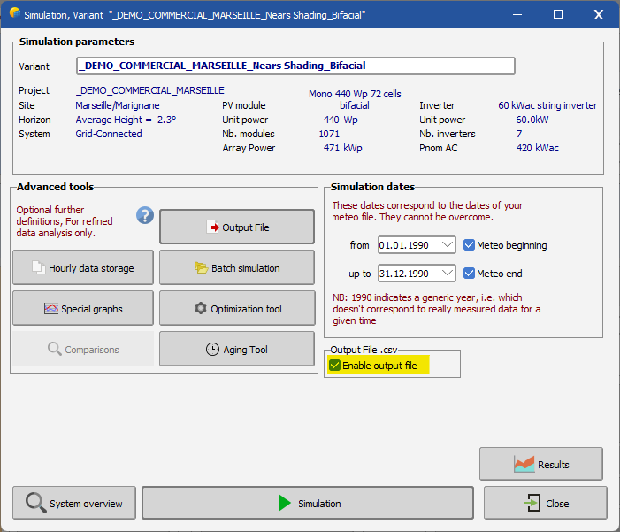
When exiting the batch definition window, and before clicking on simulation, you should also define the hourly output file format. If it is not defined and the checkbox “Enable output file” is not checked, then the hourly output may not be generated. Could your issue be due to this? -

SAT at different azimuth near shading loss
Michele Oliosi replied to Vladislav Iliev's topic in Shadings and tracking
This indeed is inconsistent. We have observed recently that for trackers that do not have azimuth zero, there is a bug for a certain diffuse shadings calculation mode. I suspect this is what is happening here. In the 3D scene, if you go to Tools > Tracker diffuse shadings definition, you can switch between the modes: automatic (=central tracker above a threshold* number of trackers / = all trackers below that threshold*) central tracker (fast) custom tracker (fast) all trackers (most accurate, slower) The "Central tracker" and "Custom tracker" modes do not work well with azimuths away from zero because the neighbor identification fails. I would suggest to use the mode "all trackers". * The threshold can be modified in the advanced parameters: Read https://www.pvsyst.com/help/tracking_diffuse.htm for more details. -

Shading losses applied after calculation of GPOA
Michele Oliosi replied to jonipa's topic in Problems / Bugs
Assuming the pyranometers are really within your array GPOA "on site" is roughly equivalent to GlobInc - Near shadings + ground reflection on front side. However, there will be some error because a pyranometer is on a single point, but diffuse shadings in PVsyst are accounted over the whole table. Pyranometers have (almost?) no IAM. Reference cells do. Therefore you should not remove IAM losses with pyranometers. -

Two values of GCR appear in the Report
Michele Oliosi replied to mgrms's topic in Shadings and tracking
Hi, I agree that the two mentions of GCR and other geometric quantities can be confusing. We will try our best to improve on this situation for PVsyst v8. The main reason some quantities are duplicate, is that in some situations they will not have the same values. Let me give an example with the GCR: — the GCR in “Sizes”: it is extracted from the 3D scene directly. This is the main “GCR” you should look at, the one which corresponds to PV area over ground area. — the GCR in “Bifacial model geometry”: as was correctly pointed out above, this depends on the parameters of the bifacial model to estimate the backside irradiance. In PVsyst the bifacial model neglects the frame around the modules, among other approximations (since the model is a 2D model, the other sizes may also differ somewhat from the 3D scene). This means that the effective GCR of this backside model may be different. It was put in the report for transparency, to acknowledge that the bifacial model is an approximation and does not 100% reflect all details of the front side modeling. — the GCR in Backtracking strategy was removed in recent versions. It was only a derived parameter based on the (sometimes manually adjusted) backtracking reference values. It was not significant enough to stay in the report. Similar confusions are present for other size parameters. We are gradually improving the situation in the report by being more explicit. One of these changes that happened rather recently is the Pitch and Width for the backtracking controller, which are now explicitly noted as “Backtracking pitch” and “Backtracking width”. This denotes that they can be different from the actual parameters of the trackers. -
Hello! Sorry at the moment it is not possible to simulate a variant with multiple orientations and the bifacial model. For a carport, if the orientations are not too different, I would suggest running a variant with a single orientation (the average one) to at least get an approximation for the bifacial gain. This will complement a “monofacial” simulation run with the 2 orientations.
-

Electrical shading losses: partition model
Michele Oliosi replied to Michele Oliosi's topic in Shadings and tracking
Version 7.4.6 further improves the evaluation of electrical shading losses by correcting the bottom cell strips positioning for NS-horizontal-axis trackers, tilted-axis trackers, and EW-frame trackers. In version 7.4.0 to 7.4.5, the bottom (and top) one-cell-wide strips were drawn incorrectly along the short side of trackers. Version 7.4.6 corrects this and draws the one-cell-wide strips along the longer edge of the trackers. This correction will drive electrical shadings down slightly for projects with electrical shading losses, trackers, and an irregular topography. This mitigation of the losses comes on top of a conservative model, thus moving towards more accurate values, in general. As a consequence, especially for projects with NS-axis SAT (and other less common trackers noted above), it is advised to update to 7.4.6 and run key simulations to obtain more accurate results. -
Just to complement the discussion, we have gone through this tutorial but are a bit puzzled as to why you would need to do two simulations and not just one. I think we are missing some understanding about why this tutorial was written, to begin with. When you choose the TFT option in PVCase this just seems to change the export to PVsyst. This is done in a way that splits “Terrain-following” trackers which have a further articulation into smaller trackers so that PVsyst gets the number of modules right. In my view, then setting up the partitioning definitions on these trackers is OK. From what I understand, there is a worry that since partitions are limited to a single table in PVsyst, in the TFT scene, they do not represent well “a string”, i.e., the shading electrical mismatch calculation will underestimate mismatch effects. However, in general, shades caused by the topography are quite irregular to begin with. Since PVsyst's partitioning approach in version 7.4 is conservative for these cases (we even advise reducing the fraction for electrical effect if shadings are too irregular, based on module layout results for example), slightly reducing the shading electrical mismatch losses by splitting the partitions lengthwise is not going to put you in tension with the reality of the field or loss mitigation. Moreover, if you don't use the TFT approach, the tables will be longer and straight, i.e., I am not sure how well the electrical shadings are modeled in this non-TFT case. Since you are diverging from the real geometry of the tables, I wouldn't take results calculated without the TFT as a reference for the electrical shading loss.
-

Connection of modules with different azimuths or inclinations.
Michele Oliosi replied to Georgy PM's topic in How-to
Dear Gregory, This seems like a very good approach, I see no inconvenient in applying it to other subdivisions. Of course, keep in mind that this is an approximation, but that will give you a good estimate of orientation mismatch within a string. -

Simulations of simple vertical bifacial systems on a tilted ground
Michele Oliosi replied to Hila's topic in PV Components
Indeed, in reality, there will be a small impact on the reflected irradiance if the ground is tilted. However, the bifacial 2D model in PVsyst does not include these effects yet. -
Development of version 8 took longer than expected. Indeed, this time “This year” should be a more trustworthy statement.
-
Dear Spencer, No, at the moment there is no real possibility to increase the amount of electrical shadings with the model of electrical shadings in partitions. It's an excellent point which we should address. The worst case value in the model is when there is only a single partition per table. But if due to the wiring, a shade on one table deactivates several tables, that cannot be modeled with the partition model. A workaround could be to define larger tables (across the same row). But in case of strings over different rows, I really don't see how to solve the problem with the partition model. The only way in PVsyst would be to go with the module layout model, but for large scenes it will take quite a lot of time. If you send us some examples (screenshot or better full project) we may be able to take a more detailed look, but I'm not sure what can be done.
- 1 reply
-
- shading scene
- partitions
-
(and 1 more)
Tagged with:


