
Michele Oliosi
-
Posts
824 -
Joined
-
Last visited
Everything posted by Michele Oliosi
-
Yes, we differentiate between mismatch caused by shadings (= electrical shading loss, ShdElec) and other types of mismatch (MisLoss), e.g., due to the quality of the modules. If you use “mixed orientations”, i.e., strings that have different orientations connected in parallel, there can also be a mismatch due to that (MixLoss). All these variables are given as hourly values, if you run a simulation with output file https://www.pvsyst.com/help/output_file.htm
-
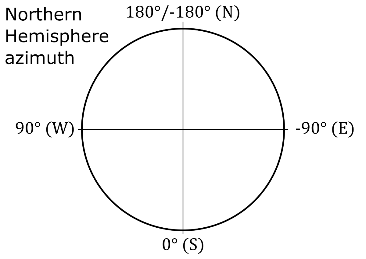
Why 0°? Southern facing side will have an azimuth of -90° (E) + 42.2° = -47.8°.
-

New to Batch, no CSV created plus how to
Michele Oliosi replied to John Dozla's topic in Simulations
Hi, I see. I don't think you need the batch mode for this. The batch mode allows you to change programmatically system and geometric parameters. But since you have just a single “weather file” (equal to or including your 5 days) you just need to run the simulation once, so no need to vary parameters. You probably would like to produce an hourly output CSV (https://www.pvsyst.com/help/output_file.htm), or a daily output CSV (same interface). There you can choose output variables such as PR, temperature corrected PR, etc. The most important step is to import your weather data. This works better if your whole weather data has more than 5 days. Just import all the weather data (up to one year) with the custom file import https://www.pvsyst.com/help/meteo_convdialog.htm to create a MET file. Then define your hourly/daily CSV output, and run the simulation. Do you need to import array temperatures as well, or should these be modeled? In the MET file creation procedure, you can also import array temperatures. To then use them in the simulation, you should then go to the Detailed losses > Thermal parameters. There you will find a checkbox that allows using imported TArray values. -
Eastern side of roof azimuth = -90° + 6.1° = -83.9° Western side of roof azimuth = 90° + 6.1° = 96.1°
-
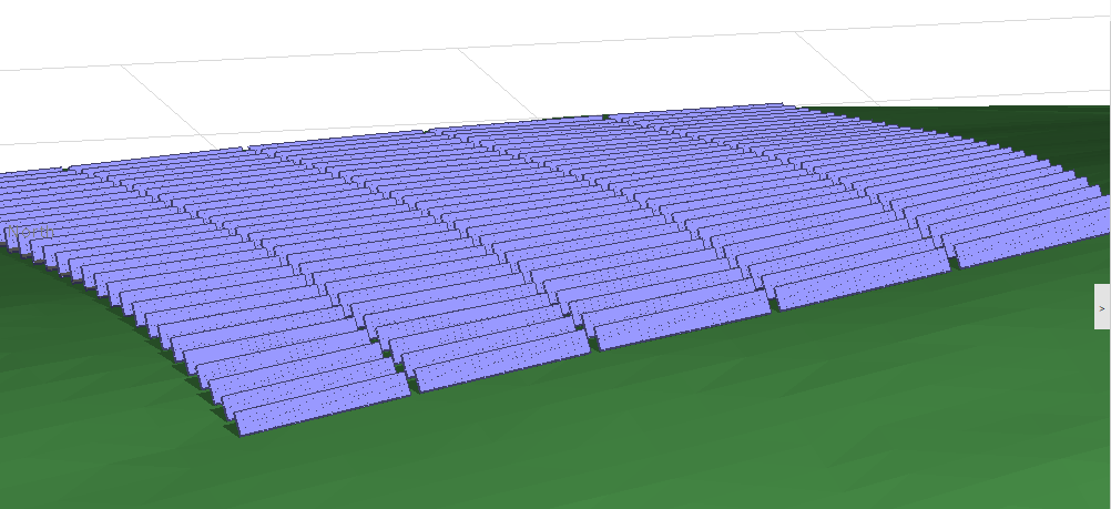
In the 3D scene in PVsyst you can import trackers that follow complex slopes, or create such a scene for example with the zone tool. At the moment, PVsyst will calculate the average orientation and apply this orientation to all trackers for the tracker rotation determination (including backtracking), irradiance transposition, and incidence angle modifier. This leads to small averaging errors. However, the shading determination, as shades are projected on individual trackers, is quite precise. With backtracking, the assumption of all trackers moving with the same parameters forbids simulating more advanced “terrain-aware” algorithms. Usually, these algorithms are proprietary and terrain-dependent, which has made them difficult to model in PVsyst (but this may change in the future, hopefully). The backtracking algorithm in PVsyst is therefore comparable to more advanced algorithms only as a first approximation, and is by nature more conservative since there will be more remaining shadings than with a more advanced algorithm.

-
New to Batch, no CSV created plus how to
Michele Oliosi replied to John Dozla's topic in Simulations
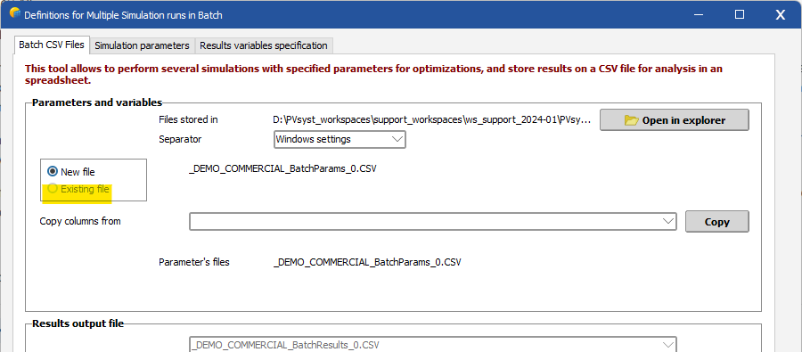
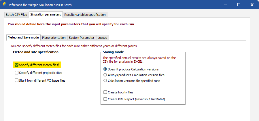
Hi ! I am not sure what is the intent in using the batch mode. Do you have several years of operation so that you need to run several simulations? Regarding the CSV, you can check the location of your workspace. There should be a sub-folder “UserBatch” in which the batch mode CSV parameter files are stored. If you don't get a new message each time, I assume this is because you have chosen the option “Existing file” in the first tab (which defines the parameter file): Note that you need writing permissions for this folder on your system to create files in this folder. As mentioned before, I am a bit puzzled as to why you require the batch mode. But assuming you want to enter “measured” input data, you can do that by changing the MET file via the batch mode. A prerequisite is to import the measured irradiance and temperature data into a MET file. See this page for more information: https://www.pvsyst.com/help/meteo_convdialog.htm In the batch mode window, you should look for the option “Specify different meteo files” on the second “Simulation parameters” tab. In the parameter CSV, you can then enter the name of the .MET file in the corresponding column.
-
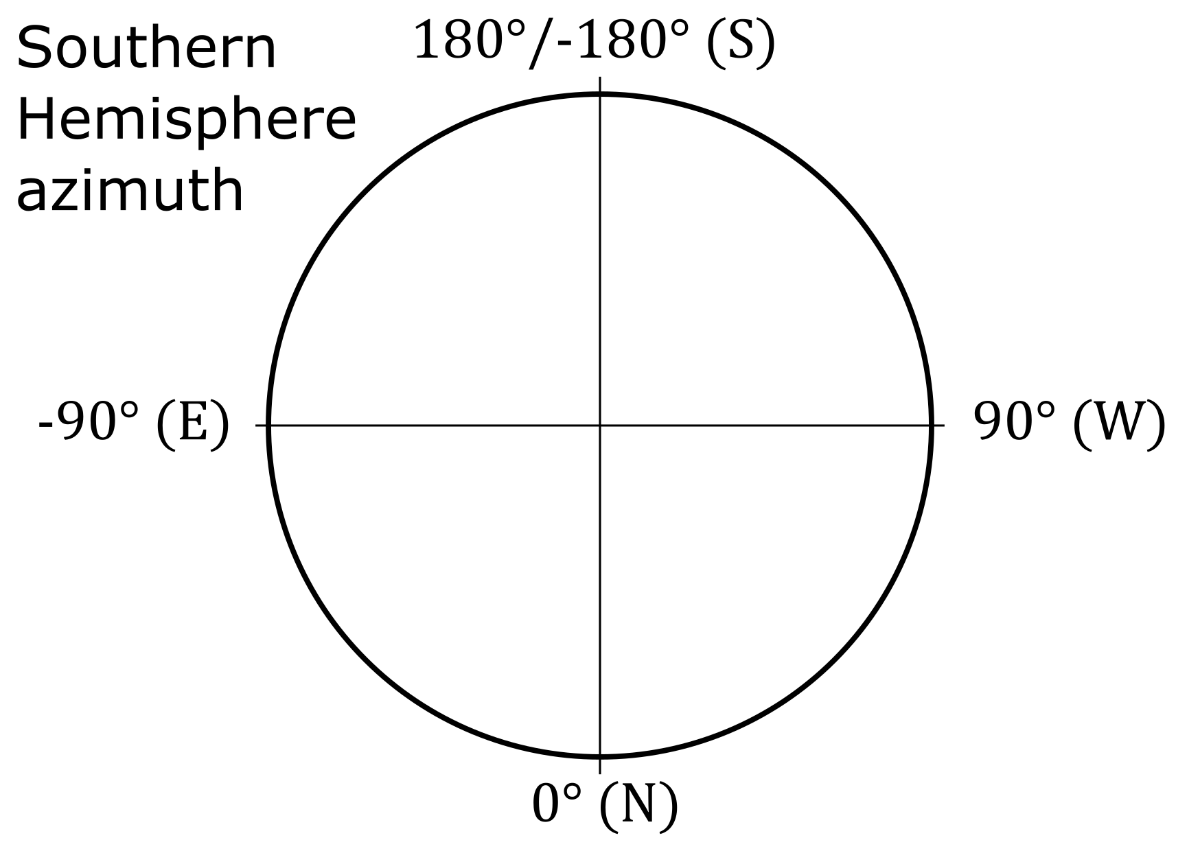
Hi, I am not sure how you count your degrees (where is 0?, what is the direction of positive angles?), but I am sure it should be easy to figure out using a drawing.
-
Note, in your situation the strings that are on two orientations are not connected in parallel, because they are connected to separate MPPTs ! Their voltages are independent. So the mixed orientation is not the correct way. The following is correct, you have checked the multi-MPPT feature checkbox. But you should not use the mixed orientation here. You should instead define four sub-arrays (one for each orientation, with 1 string each, and 1 MPPT each). You should then use the orientation power-sharing (https://www.pvsyst.com/help/powersharing.htm) functionality.
-
In the Northern Hemisphere, South is Az. = 0. In the Southern Hemisphere, North is Az. = 0.
-
Mixed orientations can only put different orientation in parallel, not in series. So it is not really equivalent. We will work on this limitation in the future but I cannot give you a definite schedule.
-
After analyzing your project, I have found that most of the sub-arrays in your system are in an erroneous state, i.e., they do not have the “power-sharing” flag activated. This may happen, for example, if you defined the “power-sharing” once but then switched to not using the multi-MPPT feature at some point. An easy way to correct the state of all sub-arrays is to go to the “power-sharing” window, and click twice on the power-sharing checkbox to deactivate and reactivate it. This will reset the flag for all concerned sub-arrays. On our side, we will try to fix the program to make sure that these situations do not happen anymore.
-
This is the loss on one day (the selected day). No, the shading factor table represents the loss for a particular sun direction. There is no temporality involved. It cannot be easily converted, you need to run the simulation to convert it to a yearly loss. It is the solar azimuth angle (negative for east, zero towards south).
-
Electrical shading losses are the total losses due to shadings. Beam linear loss is the loss of irradiance due to shading the beam irradiance. This latter is accounted in the "electrical" loss.
-
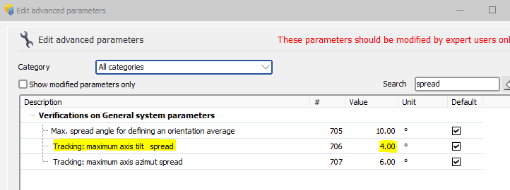
This error message was meant to be present in the previous versions of PVsyst but a bug prevented it from appearing. This has been fixed in the latest version of PVsyst, that’s why you see the error message now. To get rid of the error message, you can go to the advanced parameters, search for “spread” and modify the following value: I hope this helps. Note that cases which have a very large tilt spread may induce a certain uncertainty in the transposition calculation.
-
Cell Temp versus Ambient temperature in string voltage sizing
Michele Oliosi replied to IB31's topic in Simulations
Regarding the “Lower temperature for absolute voltage limit”, since this is a safety condition, we make the hypothesis that the cell temperature is the ambient temperature (which corresponds to the highest possible voltage). It is customary to put the lowest possible ambient temperature over several years. The other temperatures are usually not very constraining, so it is okay to put a rough estimate there. -
At some point, yes. But it is not too hard to correct the error in the current version. Instead of using the mixed orientation, you can define two subarrays with one MPPT and one string each. Then you can combine them in the string configuration, I think.
-
Hi, and happy new year as well ! This is a missing feature with our Huawei optimizer string configuration interface. At the moment, it is not compatible with the mixed orientation feature. Without optimizer, this would work. I will file a ticket for this missing feature.
-
Hello, Are you running the latest version of PVsyst ? If yes, if you can send your project at support@pvsyst.com, that would greatly help us in figuring out the issue or bug. Thanks in advance
-
Vertical E/W bifacial system with different orientations
Michele Oliosi replied to Kris's topic in Simulations
Hello, No, at the moment it is not possible to have two bifacial orientations. This will only be possible in version 8, to be released at some point (in principle in the first half of) this year. The annual yield will not change much if you use only one orientation, though, unless you are overloading your inverters. However, the hourly distribution will change, of course. -
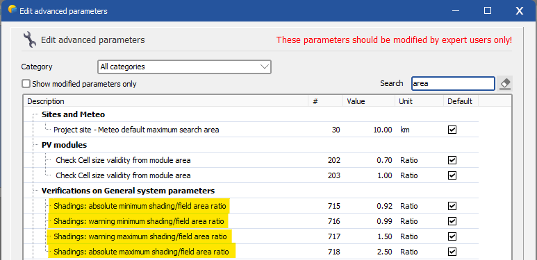
Hi, Unfortunately, at the moment, PVsyst doesn't handle well (in terms of backside irradiance) situations without a pitch. However, there are some workarounds for this issue. You can either: Use the “unlimited sheds” orientation, and define a large (e.g., 50m) value for the pitch. Keep the 3D scene, but duplicate all objects. Then you can place the copied objects far away to the east or west. This artificially generates a large value for the pitch — a situation in which the number of “rows” doesn't matter anymore. PVsyst may then throw a warning regarding the mismatch between 3D scene PV area and System PV area. This warning can be bypass via the main window > Settings > Edit advanced parameters, with the following parameters:
-
Hi, we actually checked, and it is not a regression but rather a case we didn't account for, sorry about that. You probably have single fixed tables defined in your 3D scene ? In that case indeed the functionality is missing (and always had)… We will correct this in the future. If you have trackers, or (the PVsyst PV object that is named) arrays of tables, then it should work.
-
Why does the module layout tool show multiple rows?
Michele Oliosi replied to Vera's topic in Shadings and tracking
The module layout view is a rough representation of your 3D layout. The fact that row#1 col#1 is below the others is just to avoid overlaps, it has no impact on the simulation. What counts is the 3D view. -
This is not possible currently (not possible to have trackers and fixed in the same simulation in version 7). I would advise running both variants without grid limitation. You can define an output file (https://www.pvsyst.com/help/output_file.htm) for each of them. Then combine the output powers for each simulation step. You can then apply a grid limitation in another tool, e.g. in excel.
-
how can i connect trackers in series in PVsyst shade scene?
Michele Oliosi replied to Vera's topic in Shadings and tracking
The shadings seem really negligible, because even on 21st of December (worst case), you have only 7.5% electrical loss. You mention, “the lowest production should control the current and constrain the specified production”, this is not necessarily true, thanks to bypass diodes. I think in this case, the bypass diodes are mitigating part of your electrical shading losses. The blue message in the module layout tool is a bit misleading. What it should mean is that you can optionally review the shadings at specific days in the year (assuming clear sky conditions) using the “Shadings 3D” tool. This tool is however just for review. What matters in the end is validating the module layout assignations (you don't need to go to the “Shadings 3D” tab at all if you do not want to review), and running a simulation. You can check that shadings have been computed according to module layout definitions in the simulation report. -
Hi ! Except notably for irradiance transposition (by orientation) backside irradiance modeling (one bifacial model for the whole system in v7), and shadings if not using the module layout, (e.g., if “according to strings” or “linear” the shadings are calculated by orientation) the calculation is mostly done separately, sub-array by sub-array. I will try to summarize this as a table: Mixing / Model Note 3D scene without Module layout 3D scene with Module layout modules of different ratings, same manufacturer and series Defined as different sub-arrays OK, but shadings are averaged over all modules in the same orientation OK modules from different manufacturers, but same physical size Defined as different sub-arrays OK*, but shadings are averaged over all modules in the same orientation *Bifaciality: not ok if rackings are not the same size OK* *Bifaciality: not ok if rackings are not the same size modules from different manufacturers, different sizes Defined as different sub-arrays OK, but shadings are averaged over all modules in the same orientation OK multiple racking configurations, e.g., 1P and 2P OK* *Bifaciality: not ok if rackings are not the same size OK* *Bifaciality: not ok if rackings are not the same size fixed tilt and SAT racking Not possible currently (→ v8) bifacial modules with different bifaciality factors Defined as different sub-arrays. Bifaciality factor is averaged between sub-arrays following an average weighted by DC nominal powers. No particular issue with shadings since these do not impact backside irradiance modeling currently No particular issue with shadings since these do not impact backside irradiance modeling currently bifacial and monofacial modules Not possible, unless bifacial model is deactivated bifacial and monofacial modules, where we trick PVsyst by editing the monofacial module PAN to make it bifacial with a bifaciality factor of 0 Defined as different sub-arrays. Bifaciality factor is averaged between sub-arrays following an average weighted by DC nominal powers. No particular issue with shadings since these do not impact backside irradiance modeling currently No particular issue with shadings since these do not impact backside irradiance modeling currently