Michele Oliosi
-
Posts
824 -
Joined
-
Last visited
Everything posted by Michele Oliosi
-
Domes Simulation. How Pvsyst makes the domes simulation?
Michele Oliosi replied to Jorge Cobra's topic in Simulations
No, this is correct I think. Since this is GlobInc, not affected by the bug. -
Hi, indeed, we have noticed this issue. We will be fixing this in one of the upcoming patches. Thank you for the feedback !!
-
Hi, this is likely because of the diffuse shading losses calculation. In version 7.4.8, you can check the details from the 3D scene window > Tools > Trackers diffuse shadings definition. If it is automatic, there is a chance that by ungrouping, PVsyst picked a representative tracker for the calculation (see the “central tracker” choice), which is not really representative. (2% losses is more realistic !) See https://www.pvsyst.com/help-pvsyst7/tracking_diffuse.htm or https://www.pvsyst.com/help/project-design/shadings/calculation-and-model/diffuse-losses-with-tracking-systems.html for the v8 help.
-
Domes Simulation. How Pvsyst makes the domes simulation?
Michele Oliosi replied to Jorge Cobra's topic in Simulations
Only the intermediate results are incorrect (...Trp, BeamInc and CircInc), the other results including the final production are correct already. -
Domes Simulation. How Pvsyst makes the domes simulation?
Michele Oliosi replied to Jorge Cobra's topic in Simulations
There was a bug that prevented variables ...Trp, BeamInc and CircInc from accumulating properly for a multi-orientation situation. We will update this for version 8.0.8. -
Mismatch Loss for Back Irradiance in Help Menu Example
Michele Oliosi replied to kjs55's topic in Suggestions
I confirm essentially what you mention. Thank you for the review 🙂 You are right, there are some updates to be done in the help. For the V8 it's simple enough, not sure whether we can change easily the v7 one. -
Indeed !
-
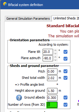
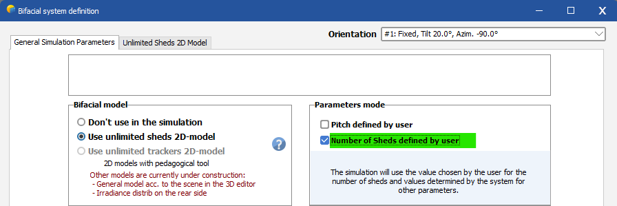
This post aims to present the main differences an user can encounter when using PVsyst 8.0.7 compared to PVsyst 8.0.6. Thin objects In versions 8.0.0 to 8.0.6, PVsyst did not calculate correctly the electrical shading losses for thin objects. This problem could be identified by inspecting the shading factor tables, showing inconsistent values when selecting “Thin objects table”: The calculation in PVsyst 8.0.7 now takes these properly into account. Electrical shading losses may be modified in your projects with thin objects because of this. Bifacial systems Several changes will affect projects with bifacial modules. No fundamental changes were made to the model, but default values and parameter labels have been updated. PVsyst 8.0.0 introduced the possibility of defining the number of rows and pitch used in the backside geometry model manually. Previous to that, the number of rows and pitch were automatically extracted from the orientation definitions, or from the 3D scene when available. This automatic evaluation was not always correct. For unlimited orientations, the number of rows used in the bifacial model is now forced equal to the number of rows in the orientation menu. Related fields in the bifacial menu cannot be edited anymore. See below in 'New Warning' for the behavior when opening a variant with simulation results that were using a user choice for the number of rows. Default number of rows The estimate for the number of rows has been improved. For example, in version 8.0.6, the number of rows returned the total number of trackers. This is now fixed. Note that with complex 3D layouts, this estimation could still be not fully representative of your system. This is why it is possible to override the number of rows manually. Reading PVsyst 7 or earlier simulation results Variants stemming from PVsyst 7 or earlier did not store the number of rows parameter. When reading the results in PVsyst 8.0.7, for variants where the number of rows cannot be determined retroactively, the report will show an “NA” note for the number of rows. If a new simulation is run, the number of rows will be set to the new default value. New warning A warning will be displayed when the user sets a non-default value for the number of rows in the backside geometry model. The PVsyst estimation for the number of rows is based on the 3D scene layout when available. With complex 3D layouts, this estimation could be not fully representative of your system. In such a case, this warning can be ignored. For the rare cases, where a variant with an unlimited orientation contained a user choice for the number of rows in the bifacial model, this warning will also appear if the variant contains simulation results, to make sure that the report and results correctly reflect the settings that have been used for the simulation. Since this option is not available anymore in V8.0.7, it is not possible to change the number of rows in the bifacial window. However, when running the simulation again with V8.0.7 the number of rows will toggle back to the default value, which is the number of rows defined in 'Orientation'. EW axis and NS-frame trackers When the azimuth of the axis was not zero, shadings were not properly calculated. This meant that the “Near shading losses” were not reliable. This has been corrected. Grid limitation and trackers In versions 8.0.0 to 8.0.6, a bug when combining grid limitation and the tracking algorithms “irradiance optimization”, “wind stow” or "seasonal tilt" prevented these algorithms from being properly applied. This has now been fixed. This may increase transposition gains in your variants, as irradiance optimization now corrects the tracker motion to maximize irradiance properly.

-
Shading loss factor without 3D Scene
Michele Oliosi replied to Umut's topic in Shadings and tracking
No, sorry, that is not possible. This would invalidate all hourly results. -
Okay ! Then yes I would divide them by the related maximum power. DC cabling loss -> DC capacity AC cabling loss up to transformer -> AC capacity AC cabling loss transformer to POI -> transformer capacity
-
Weird Thin Objects Electrical Shading Factor in PVsyst 8.0.6
Michele Oliosi replied to AutoRob's topic in Problems / Bugs
The thin objects shadings does not work in 8.0.6. Sorry for the inconvenience, we noticed this only recently. This should be patched for version 8.0.7. -
But your power systems study is for an STC operation ? Or for realistic conditions.. If it's the latter, these kW losses will be underestimated if you compare them to the capacities.
-
One quantity that is easier to export for the resistance losses specifically is the resistance. If you have this value you can transfer it to PVsyst easily.
-
Hi, For ohmic resistance losses, it is difficult to convert the report total losses to a % at STC. Indeed, at STC the current is higher, and therefore the losses should be higher as well. This dependence on the external conditions is also marginally present for other losses as well. When you say that the losses are given in kW... do you mean the PVsyst report or the power systems study ?
-
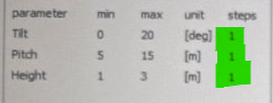
You seem to have defined only one iteration step ? As a consequence, you cannot have any trends. You need to increase the number of "steps" to evaluate the simulation over a scatter of parameter space points.
-
Different Global Inc. plane with same meteo data
Michele Oliosi replied to Vinh Thinh's topic in Simulations
Yes that's it ! -
Different Global Inc. plane with same meteo data
Michele Oliosi replied to Vinh Thinh's topic in Simulations
The average tilt angle is quite different. this means that the trackers are arranged differently ? If so the tracking motion will also be different. If the plane orientation changes, then transposition gains will also change. -
Different Global Inc. plane with same meteo data
Michele Oliosi replied to Vinh Thinh's topic in Simulations
Hi, can you share the pages with "General parameters" ? To be able to say for sure we would need to know the typology of your array of trackers / tables. I suspect you have the irradiance optimization on ? If so, the change may be due to the shading evaluation being overall more precise. If you would like for us to check in more details you can also send your project over at support@pvsyst.com -
Hi, Yes, indeed, the “All trackers” option will average the shading factor tables on all the trackers in your scene. This is evaluated at 7 different tracker angles, integrated over sky directions, and then interpolation profiles are then generated. In the end, you have a profile that takes in a tracker angle and gets out a shading factor for the diffuse and albedo components. In general, the best is to use the “All trackers” option. Since it takes the whole scene into account, it is the most representative. Besides, the “central tracker” may or may not choose the neighbors properly, i.e., it is good to check the selection automatically made by PVsyst when using this latter option. The only downside to the “All trackers” option, is the long calculation time at the “simulation initialization” stage.
-
Getting error when trying to import Standard weather data file
Michele Oliosi replied to Mike99's topic in Meteo data
It's difficult to say whether it's useable or not, there could be some cloud enhancement effect for example. Some locations also have higher extreme Ktcc values. But at the very least, it raises the question of the calibration of your sensors. If possible, I would suggest looking at possible problems on the hardware and data collection side. But before this, I would suggest correcting the time shift (as noted 61 minutes of time shift are found) directly in the file. As noted here: https://www.pvsyst.com/help/meteo-database/import-meteo-data/pvsyst-standard-format/index.html you can use the tags: “#Hour Shift;" and “#Time Shift;” to apply the time shift when importing. This may improve the results of the import. -
Pitch between tables is not sufficently homogeneous
Michele Oliosi replied to Edwin Tellez's topic in Simulations
@Edwin Tellez In this case, you should define two "identical" orientations. Assigning one sub-array to the first and another to the second, corresponding to the 2V and 3V arrangements respectively, will let you combine the two geometries. In v8, it is possible to work with different backside geometries in the same variant ("Bifacial models") provided they are in different orientations. -
@Vamsee Since v8, it is now possible to have multiple bifacial orientations, or a mix of bifacial and monofacial orientations (the latter do not require defining a backside geometry). As long as they belong to different orientations, you can have a sub-array with bifacial modules, and another sub-array with monofacial modules. However, it is not possible to define spectral corrections sub-array by sub-array. It is therefore not really recommended mixing CdTe and Bifacial modules, at the moment. I will add this feature to our request list.
-
Originally I thought your pyranometer may not have been at the top of the row. This means that it would have “seen” other PV rows in its zenithal hemisphere, even in hours without direct shadings (which you could filter out). This is accounted for in the diffuse shadings. But in your case, the diffuse contribution to the measured irradiance is unshaded by mutual shadings.
-
2) Ah yes, this makes sense. I agree with your suggestion.
-
Can’t open bifacial module with solar farm dome
Michele Oliosi replied to Pattarporn's topic in Problems / Bugs
Hi, at the moment PVsyst cannot simulate the backside irradiance for domes. Note that in general the bifacial gain of dome structures is negligible, unless they are installed very high above the ground.