
Michele Oliosi
-
Posts
824 -
Joined
-
Last visited
Everything posted by Michele Oliosi
-
 There can be some differences between 7.4.8 and 8.0.5, these are explained by improvements of the modeling. However, in your case they seem a bit large (still about 0.5% or so in total). This might be normal or not, to be sure we would need to take a detailed look at your project. For this you would need to send it to support@pvsyst.com (mentioning this forum post). Note that the zip archive should be made to contain all necessary files, for example by using the "Export" functionality in the projet window.
 -
Can you go to Near shadings > Table, and click on “recompute” ? This should update the shading factor table. Let us know if the issue persists.
-
2) I suspect that this pyranometer placement is biased towards higher irradiance than what is actually incident on the backside on average. Indeed, because of mutual shadings, the irradiance is not homogeneous on the backside. The lower end receives less light than the top. For the front side, PVsyst outputs GlobInc, which is the irradiance in the plane of array, without yet applying mutual shadings. For the backside, this is not the case, mutual shadings are already accounted for in the different irradiance contributions. For the sake of the comparison with the measurements, I would suggest defining a different variant in PVsyst that exchanges the front and backside. In this way, you can compare with BeamInc + CircInc + DifSInc + ReflFrt +( - HrzBLss - HrzCLss - HrzDLss), the latter parenthesis if a horizon exists, of this variant with the real backside measurements. Note that because the backside pyranometer sees other rows, the albedo contribution should be removed. For the front side, since it is in the front row, there is a far albedo contribution: BeamInc + CircInc + DifSInc + AlbInc+ ReflFrt +( - HrzBLss - HrzCLss - HrzDLss - HrzALss). 3) I am a little surprised by the low backside to front side irradiance ratio. Is the azimuth not 90°?
-
Hi ! We have unfortunately discovered two bugs that plagued version 8.0.4 and previous. This affected in prevalence average orientations on a complex topography, or whenever there were mesh shading objects such as the fences. We fixed these in version 8.0.5. Please let us know if this fixes the issue, thanks in advance !
-
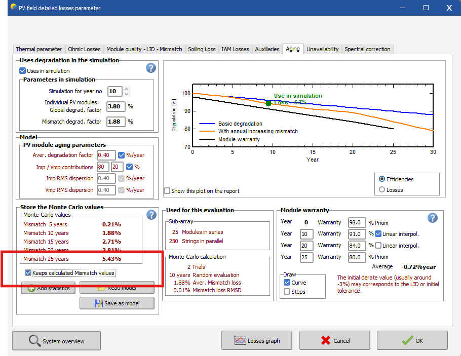
Thank you for reporting this issue. If you compare the loss diagrams, this seems to be related to a discrepancy in the maximum voltage threshold loss of the inverter. This might be related to the degradation definitions. Can you check whether the checkbox “Keeps calculated Mismatch values” in Detailed losses > Aging has been checked ? If not, this may be an explanation, as the array voltage point may be slightly different between the two runs.

-
Comparison of "Near Shadings" value in version 7 and 8
Michele Oliosi replied to FUJITA_ANE's topic in Problems / Bugs
Yes. A bug was corrected in update 8.0.5, that afflicted cases where an averaged orientation had a large orientation spread. In these cases, the shading factors were pessimistic for low sun heights. Now things should work properly. -
Dear Luis, Regarding the albedo, did you enter it in the bifacial model? For the purpose of backside irradiance calculation (and also for the light reflected from ground to front) the albedo should be entered in system > Bifacial system > first tab. Other than that, I wonder about your pyranometer placement. Do you have some images/details on that ? There could be some differences depending on the height at which they are placed (and also the pitch between your rows). Finally, could you share a screenshot of your loss diagram ?
-
1) I think this depends on how the 3D scene was defined. If they are defined as individual tables, they will be turned each around their own center. Each “array of tables” will be turned as one object with a common center to the whole array. 2) No, the azimuth is overridden. In general, when you have such questions on “what does PVsyst do in the optimization tool / batch mode” the best way to check is to use the batch mode. In the batch mode, you can modify the same parameters as in the optimization tool, and more. It has one interesting additional option, which is to store a variant corresponding to the batch modification: This allows to check whether the modifications make sense, afterward.
-
Albedo and Diffuse Factor in horizon losses
Michele Oliosi replied to Gustavo Pianovski's topic in Shadings and tracking
HI, there seems to be a bug that shows the factors as 1.00 even in cases where they are not 1. The displayed values are just updated when you enter the "Diffuse factor" tab in the horizon window. We will be looking into the bug. They are in any case internal variables, indirectly calculated from the orientation and horizon profile. You cannot set them manually. It is not equivalent to the far/shadings and horizon loss. These will in fact depend on details such as the exact weather data and diffuse to direct ratio, the sun trajectory, orientation of the tables, etc. This means that you cannot find a one-to-one correspondence between these factors and the far shading losses. -
In the "auto altitude" tool you can also change the height of the objects above the ground. This will prevent having to change the height of the ground afterward.
-
@Alberto Cerrone for an unrelated question, you can check other topics on the forum or create a new topic, please. There is no need to consider 3 arrays as one string (it is actually not possible, unless you use the detailed calculation model via the “Module layout” option). The partition model is an approximation adapted to regular row arrangements. In such a situation, there is not much difference in having 3 partitions or 1 long partition.
-
We are aware that since December 18th, PVGIS has modified their format for the TMY output, which has affected the functionality of our API call. You can find detailed information about this change in their release notes here: PVGIS Updates, Bug Fixes, and History. We are actively addressing this issue, and a fix will be included in our next release, planned for mid-January. In the meantime, you can use the following workaround to bypass the modified format: Open the Databases window and click Known Format. Choose PVGISv5 Hourly Time Series Direct Import. Define your site by selecting a location from the list or using the interactive map. Import the available data from PVGIS by clicking Import. This will generate .MET files for each available year. Normally you would not run the simulation for a specific year, but an average/typical year based on data from a larger time period. After saving the .SIT file, you have the option to either create a synthetic year based on monthly averages, or to create a typical metrological year – TMY To create a synthetic year, click on the button "Synthetic gen." and Execute Generation. You can read more about the synthetic data generation in the following help page: https://www.pvsyst.com/help/physical-models-used/synthetic-data-generation/index.html?h=synthetic+dat To create a TMY, close this window and click TMY generation in the Databases window. In the dropdown list in the top, you can find the site you just created and all the .MET files for the specific years at this site. Pick a Generation method and click Save TMY. You can read about TMY data generation in the following help page: https://www.pvsyst.com/help/meteo-database/tmy-data-generation/index.html?h=tmy+generation These files will be saved in your workspace and can be used for simulations as usual.
-
Hello ! The issue is that PVsyst is not really yet able to define a bifacial model when there is only a single table in the orientation. While it may have seemed to work in previous versions, the calculation was probably not correct. This issue will be solved in an upcoming patch. Until now, the workaround to define a single table with a bifacial model was to put two tables in the 3D scene, and distance them enough so that there would be no shading between them. Here, since there are shading objects and other orientations, this is a bit more tricky. What I would suggest is grouping the single table from orientation 5 with those of orientation 3 (which have a very similar orientation). To do so, you can enter “Orientations management” and drag and drop the table from orientation 5 to orientation 3. If prompted, choose “create average orientation”. Another option is to go to the List and Management of objects (or CTRL+G) and simply use the drop-down menu to select the orientation 3 for this table. By putting them in the same orientation, you will be able to define a single “average” bifacial geometry model.
-
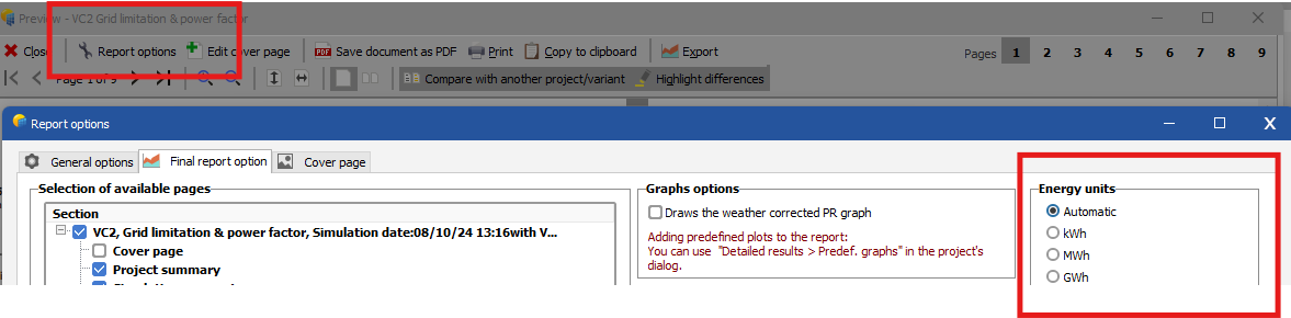
Hi, You can change the units in the report options:
-
Hello ! A) ReflFrt is not already included in GlobInc. It is okay to add it. Instead of GlobInc i would suggest using GlobHrz, if you have a horizon line. Moreover, depending on the positioning of the pyranometer, you may want to deduct the diffuse shading losses ShdDLss. B) ReflBck should not be added like you suggest. This is because it is already included in GlobBak. Instead, you could add BackShd (which was deduced to get to GlobBak), as a way to reintroduce the structural shadings which probably do not affect your pyranometer.
-
Export all variant variables for the purpose of comparing independent models
Michele Oliosi replied to Pete's topic in How-to
If you have both projects and variants, you can compare the reports, but I think this still categorizes as "manually reviewing". Unfortunately, no, there is no such export of configuration variables in a way that can be parsed. We have this on our roadmap, but at the moment bug fixes and other major improvements have a higher precedence.
-
Plane of Array Vs Global Incident in Coll. Plane
Michele Oliosi replied to Tokoyoshi's topic in Simulations
Year-to-year variability can be of about 5%, and climate change can also be a factor. Comparing a couple of years to a TMY may indeed give significantly different results. However, in some cases the satellite TMY / synthetic approaches may be biased up or downwards, that also happens. I would suggest communicating with Solcast and Meteonorm about that. I am not surprised at the 10% increase, because trackers on a topography are subject to some shadings due to the differences in height, even if you have the best backtracking algorithms. Note that in PVsyst we are a bit pessimistic regarding the backtracking algorithm. Also note that the irradiance optimization algorithm, instead, is quite optimistic ! Actual trackers may never actually apply such a strategy, there is always a question of lag, rotation speed, actual sky analysis and so on. -
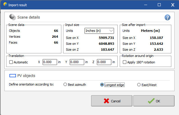
Hi, when importing, you should be wary of the following option: This will define the orientation properly. You can also try the East/West option. Note that you should not simulate East/West dome systems with a bifacial model. This cannot yet be calculated in PVsyst, a dedicated model needs to be developed still. In principle, the bifacial gain of E/W domes is negligible, unless the height of the dome is important.
-
Plane of Array Vs Global Incident in Coll. Plane
Michele Oliosi replied to Tokoyoshi's topic in Simulations
Ah you have irradiance optimisation on ! Then your movement (therefore GlobInc) could be quite dependent on the weather file. It is therefore crucial to compare apples to apples and start from the same weather file and deactivate the backtracking. Do you have the results for that case ? -
Backtracking Algorithm GCR Differs from Average GCR
Michele Oliosi replied to asanogo96's topic in How-to
dtarin's answer is on point, thanks ! -
We understand their argument and it seems reasonable. But do not have enough studies to validate or invalidate their claim. Even TGY has its own specificities compared to TMY. The impact of changing from a TXY to another should be studied further.
-
Plane of Array Vs Global Incident in Coll. Plane
Michele Oliosi replied to Tokoyoshi's topic in Simulations
I assume you are not using backtracking. Shading is not relevant for GlobInc, since it has not yet been applied. Weather can be a factor in so far that every irradiance component has a different transposition scheme. If the pattern of diffuse to direct irradiance is different, there can be differences in the transposed irradiance GlobInc. Other differences could be found in the details of your tracker definition. Are the stroke limits the same, for example ? Is there any axis tilt ? -
Issue with Shading Analysis in PVsyst
Michele Oliosi replied to Rai Augusto Silva's topic in Problems / Bugs
Hi, in PVsyst topographies are imported by default without the flag “shadow casting”. You can double-click on your topography object in the 3D scene, and tick the checkbox "Enable shadow casting”. This should fix the issue. -
Getting simulations results in 15 minutes values
Michele Oliosi replied to ramalochan's topic in Simulations
Natively, the situation has not changed. The simulation output's shortest interval is still 1 hour. However, we have planned the sub-hourly simulation in our roadmap. Moreover, as a workaround, it is technically possible to run several simulations to emulate a sub-hourly simulation: https://www.pvsyst.com/wp-content/pdf-tutorials/pvsyst-tutorial-v8-pseudo-sub-hourly-simulation-en.pdf -
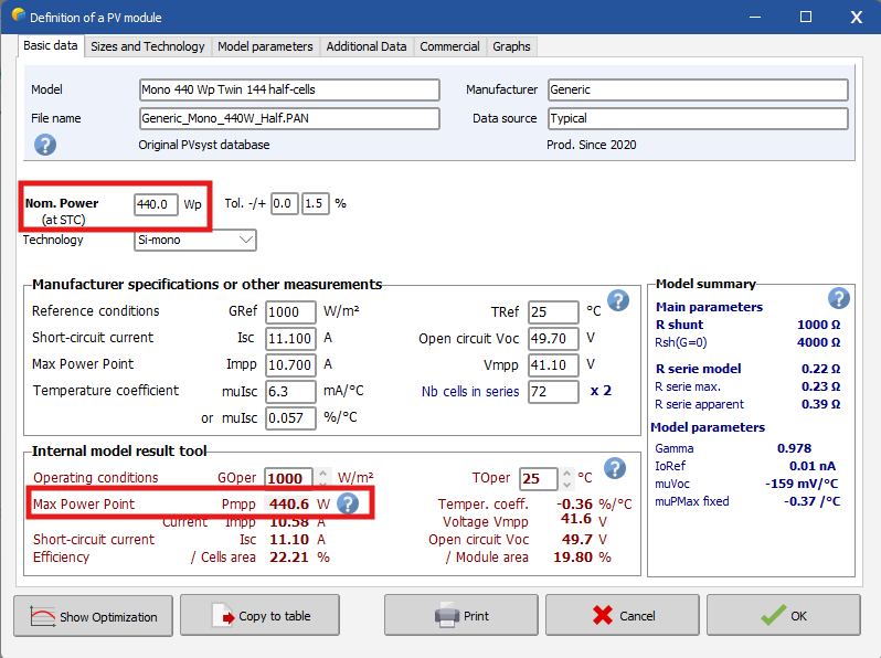
In recent versions of PVsyst, nominal array energy balance errors are caused by the PAN file definitions. Whenever the one-diode model parametrization does not reproduce the nominal rating of the module, the issue will reflect at the level of results via this warning. I encourage you to open the module definitions, and observe the different discrepancies. Note that generally the fit cannot be exactly right between both values. Insignificant differences are no problem. The problematic case is whenever the difference between the two values become important.