-
Posts
888 -
Joined
-
Last visited
Everything posted by dtarin
-
Sorry for the late reply here, just saw this. It appears HIT is classified as an unconventional technology, to which LID does not apply. It seems LID is only applicable to c-Si technology in PVsyst. Panasonic HIT modules (for example) state low LID, but not zero LID. I would suggest accounting for LID loss in the module quality factor loss.
-
You can change tilt under the orientation menu (under input parameters). If you have created a 3D shade scene, you can also set the tilt there, and update the orientation settings once you save and close the shade scene.
-

What is Constant Loss factor(Uc)? How can it be calculated?
dtarin replied to razikakbar's topic in PV Components
See: http://files.pvsyst.com/help/thermal_loss.htm https://pvpmc.sandia.gov/modeling-steps/2-dc-module-iv/module-temperature/faiman-module-temperature-model/ -
Thank you for the response. When new features are introduced or changes are made, there is a delay in the help notes being updated. Since knowing more about the changes is beneficial to all users, it is useful to come to the forums so others can understand them at the same time. Some recent examples which come to mind were the changes made to soiling ("Deep review of soiling treatment"), and the irradiance optimization tracking method. The documentation in 6.8 covers the irradiance optimization strategy, but when it was released, users were not aware of what it entailed, and thus came to the forums for clarification.
-

Backtracking with reference tracker and single tables
dtarin replied to neelesh92's topic in Shadings and tracking
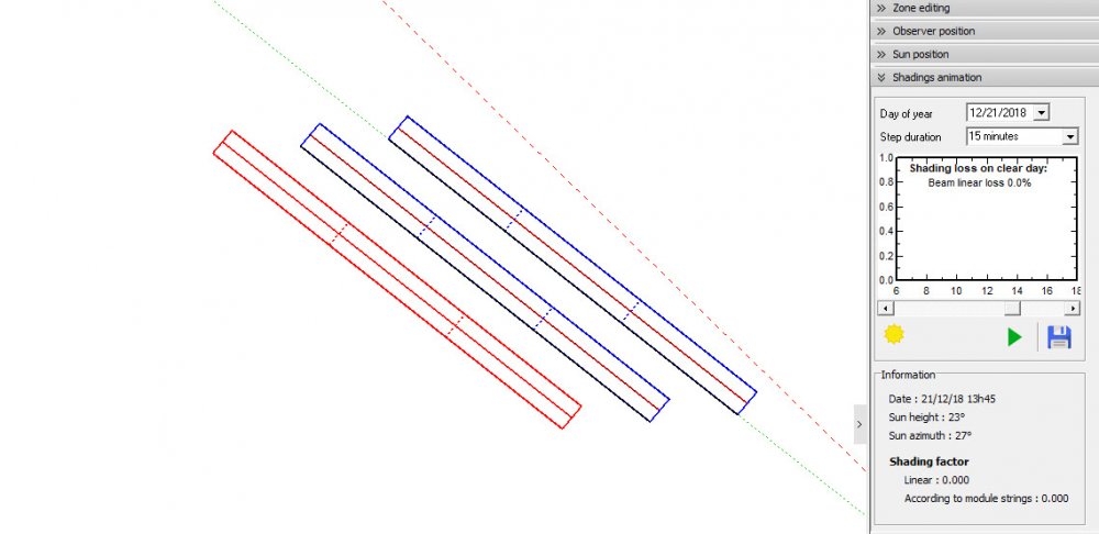
Hello, Where are you seeing the shading? In the waterfall, or in the shadings animation in the shade scene? I just tested in 6.7.9, and I have a single tracker next to a two row tracker, and backtracking is working for me. As you can see, I have selected the single tracker, showing it is not part of the first two rows. 0 shading in the shadings diagram to the right, as well as 0 electrical effect in the waterfall. Maybe your tracker isnt spaced exactly. -
Thank you for bringing this to attention. I have noticed the next to zero feedback as well from PVsyst, and moreover no reply to this thread. It would be great if PVsyst could provide a comment on their lack of attention here. Between no proper documentation for updates and no comments here, each update brings more unanswered questions.
-
Using v6.8.3, I get a horizon profile from within PVsyst just fine.
-
Check newest version released last week, thought I saw a note about PVGIS import data.
-
It was my understanding PVsyst cant simulate at all in the same shade scene trackers with different tilts, batch mode or not.
-
It looks like it is total system production, what is being sent to battery + what is being sent to grid.
-
Hello PVsyst team, Can you elaborate on the changes made with regards to soiling in version 6.8.2? The description window states: "Deep review of the soiling treatment" Thank you.
-
The Rsh and Rshunt exponential are different in my 390W PAN file, but that's not to say yours are incorrect. As long as you have your own 390W PAN file to go off of, it should be ok.
-
It looks like you are missing the cell dimensions in the PAN file (122.2 cm^2 is my guess based on the 390W). Verify you have the correct power temperature coefficient Pmpp. Also your Rshunt G=0 & Rsh dont match the 390W PAN file.
-

Chint Power Systems Inverter Stringing Trouble
dtarin replied to jstrutz's topic in Shadings and tracking
-
Hello, It is currently a shortcoming in PVsyst when defining a table size less than the width of the string (when defining partitions), as this results in lower electrical effect losses. It is not always possible to define a table size one string in width, such as cases where sites contain complex undulations or unique geometries, and a smaller table size is needed. The module layout method does not always work (https://forum.pvsyst.com/viewtopic.php?f=4&t=4334), nor is it applicable to large sites. Development to address this shortcoming by allowing smaller tables to be joined into one string would be much appreciated.
-
Yes that is problem in PVsyst. You might need to manually place them, by first setting the azimuth to face that direction, and then set the tilt.
-
My guess is that you will need to contact the inverter manufacturer for this information, as it could depend on the internal architecture of the inverter and how they have designed it to operate.
-
Yes That is correct 1) 4 H x 1 W 2) 2 H x 2 W 3) 1 H x 4 L Yes, the lowest current drives the current of the string, so in #3, when the bottom modules are shaded, the entire string has reduced output. The according to strings method of shading will capture this effect for c-Si modules (setting electrical effect to 100%).
-
I am still receiving this in 6.79 https://i.imgur.com/qt0gJ3B.jpg
-
Modules change color when you render the shade scene into realistic view. It would be nice if they changed color in all views though. https://i.imgur.com/R0AtAGg.jpg
-
Before project is run. Under project settings, when you make the change, the project will need to be saved, and will use that transposition method you selected
-
Correct, azimuth does change. If the "update orientation parameters" function is part of the process, it would update each of these parameters for each run and be able to execute is my guess/suggestion.
-
Here is another example of the PVsyst report giving different results than expected. Am I going about this the wrong way? Any help is appreciated. https://i.imgur.com/LRgv2RC.jpg


