-
Posts
889 -
Joined
-
Last visited
Everything posted by dtarin
-
I recorded a video successfully in 6.7.3, large resolution, 3 sec. duration. Running windows 7. It may be an issue with your machine.
-

Bi-facial simulation and orientation selection
dtarin replied to nitinpanwar's topic in PV Components
This value has been updated to a default if 5% (as of v 6.7.4 I think), as it was believed to have been overestimated @ 10%. I dont have any info on the shading loss factor, so can't help you there. -
It is stated in the patch notes for 6.7.5 that this was corrected.
-
Hello, We sometimes encounter stringing in the field which is asymmetric, and would like to know, would it be possible and useful to be able to model partition zones as such? Image attached for reference.
-

Bi-facial simulation and orientation selection
dtarin replied to nitinpanwar's topic in PV Components
Hello Nitin, I do not believe bifacial simulation for use with 3D scenes is yet available, and must use unlimited sheds at the moment. 1) Yes. 2) No See: http://forum.pvsyst.com/viewtopic.php?f=24&t=3544&p=8825&hilit=bifacial#p8825 -

String Inverter v/s Central Inverter : Inverter loss over nominal power
dtarin replied to Pooja.SH's topic in Simulations
Posting a snapshot of both waterfall diagrams side by side would help. Is the energy going into the inverter the same for both simulations? How about inverter efficiencies? -
Thanks for this tip, it is something we will be doing ourselves soon.
-
I would also like this feature, as I can't tell you how many times I've had to and will continue to set the report to 2 decimal places.
-
Hello, It would be helpful to be able to upload low light data for PAN file modification either by copying/pasting or uploading an excel file, rather than entering each point manually.
-

Centering Near Shadow report viewv of the 3D FV field model
dtarin replied to grouriak's topic in Shadings and tracking
Enter the shade scene builder under Near Shadings > Construction/Perspective. Zoom in to the PV plant, such that the view you want on the report is showing on the screen. Once you have that, select "save this view for the report" and then select "load report view", then exit and generate pdf. -
With the anticipation of increased use of bifacial modules in the future, it would be useful to be able to include hourly albedo data which is used in the calculations, perhaps imported with the meteo data when creating the MET file.
-
Does this mean it is now valid to model trackers with a misalignment?
-
You may need to reach out to the manufacturer for the derated value, whether it be a curve or tool they provide. I dont see anywhere in the software (OND file) which allows for elevation derate. You might then clip post-process anything higher than the derate value @ your elevation.
-
Hello, I am interested in understanding two of the bifacial modeling inputs better: rear side shading, and rear-side mismatch. Have there been any updates as far as research or studies go which shed light on providing realistic values for these inputs? It seems the PVsyst default numbers are 5% for rear-side shading, and 10% for rear-side mismatch. How were these values arrived at? Thanks.
-

unable to create tracking tilted or horiz.N-S axis
dtarin replied to anil875052's topic in Simulations
It is not possible to model trackers on a ground terrain. You can only slope them in the N-S direction using tilt. -
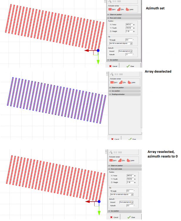
In version 6.7.2, when I select a tracker array in the shade scene and set azimuth to say 11, the array is adjusted accordingly. If I then deselect the array and reselect it, the azimuth is reset to zero. It seems to me the azimuth should remain to what it is set to.
-
Depending on the inverter you can use the multi mppt feature to model across different sub-arrays assigned to different orientations. This can be done to model different orientations, modules, etc.
-
Replacing that with average would be good (and stating it as such).
-
Hello, It would be nice if we could hide a ground CSV data like we can a ground image. I would like to keep it in the shade scene but not have it show in the report.
-
Hello, In 6.7.0, when a monthly soiling profile is used, the yearly loss factor value is also being displayed on the report. It doesn't seem to affect the calculation, but is a little misleading when reading the reports.
-

Missing zones in shade scene in 6.68 from previous versions
dtarin posted a topic in Problems / Bugs
Hello, In PVsyst 6.68, when I load a project with a shade scene utilizing multiple zones that was created in an earlier version (usually 6.63 for me), not all of the zones are present in 6.68. Usually just the first zone is, and the rest are deleted, not present at all, but all of the objects in the shade scene are there in the same manner as they were constructed in. The zones are present in 6.63 but not 6.68. I also tried saving the shade scene in 6.63 and then reloading it in 6.68 (by reading scene) and they were still missing. -

System consisting of both tracker and fixed orientations
dtarin replied to bfarzipour's topic in How-to
There is not as far as I know. You will need to create two variants. -
Thank you for the reference. However the issue I have arises when the angle tolerance is less than 1 degrees. In hidden parameters, we can define a tolerance of 0.1 degrees, but it doesnt seem possible to manually define orientations with such a tolerance. The result always reverts back to a single orientation (in my recent case).
-
Hello, I have a shade scene with ground terrain, and I'd like to divide the design up into four sections that are relatively close together in terms of average tilt and azimuth. In Hidden parameters under Detailed Simulation Verification Conditions, I have set the first six values to 0.1. However under project settings > other limitations, the minimum value allowed is 0.5 for discriminating orientation difference between shading planes, and 1.0 for maximum orientation difference for defining average (spread) orientation. What I think is happening is that the project settings are overriding the hidden parameter settings, and because my orientations are close together, the orientations I manually define in the shade scene using the orientations tool keeps reverting back to a single effective azimuth. Can the minimum values allowed in project settings > other limitations be reduced to 0.1 degrees to allow for more granularity in defining orientations?


