-
Posts
888 -
Joined
-
Last visited
Everything posted by dtarin
-
Hello, I am getting what seems to be a bug for the HV transformer definition, cannot enter generic values. Anyone else? Version 7.1.5
-
Be sure to count the number of MPPT inputs in the system definition, so that it totals to one inverter. If you have 15 mppt inputs on the inverter, you should have 15 utilized in total between the mixed sub-arrays: sub array 1: 8 mppt inputs, N strings of module A sub array 2: 7 mppt inputs, N strings of module B Total mppt inputs: 15 Total inverters: 1
-

Your PV system is not suited for the bifacial 2D model computation
dtarin replied to Gyeongil Kwak's topic in Problems / Bugs
Is your pitch uniform in the shade scene? -
Yes, I believe this has been an occurrence for quite some time.
-
Determine the power gain due to the back side through simulation, and multiply it with the front side current you would use with a monofacial module.
-
It does not include the electrical loss according to strings, as this is an electrical loss, not a light loss, and dependent on partition definition, electrical effect %, etc.
-
User NREL viewer, download the PSM TMY3 meteo file for albedo. https://nsrdb.nrel.gov/ Edit: SolarGIS also provides satellite based albedo for specific sites.
-
Are you referring to the mismatch loss? Yes, it should be lower for microinverters, <1%.
-
Hello, It would be great if users could select which variants they wanted exported when exporting a project. An expanding submenu where users check which variant to include is one example.
-
Search the forums, there are some existing posts. https://forum.pvsyst.com/viewtopic.php?f=25&t=5073&hilit=mppt Arrays 1 and 2 are straight forward. Arrays 3 and 4 in PVsyst are the two configurations for the last array. In these two arrays, you will check the mppt share box, and balance power Subarray 1: 48 strings, 33 modules in series, 4 inverters total Subarray 2: 24 strings, 32 modules in series, 2 inverters total Subarray 3: 10 strings, 32 modules in series, 5 mppt inputs (check "use mppt sharing") Subarray 4: 2 strings, 33 modules in series, 1 mppt input (check "use mppt sharing") I dont know what inverter you are using, but you can modify it to have 6 mppt inputs. Allocate 5 to subarray 3, and 1 to subarray 4. The link above should help. This will be equal to 1 inverter.
-
Hello, It would be helpful and useful if PVsyst added a button on the Detailed Results page which links to the UserHourly folder in explorer, similar to the batch simulation menu, where there is a button to open up the UserBatch folder.
-
Yes, it should match to what is stated in your OND file.
-
It is computationally intensive, and PVsyst will have difficulties with larger sites. If they are large enough, it will not work at all. 1MW is some threshold I imagine they determined in the past based on performance. In my experience, sites larger than 1MW can use the module layout method; however there still is an upper limit for how large a site can be processed, and it may depend on the nature of your model, computer system, etc., in addition to the software.
-
Hello, It would be helpful if PVsyst added a new shade scene object, called irradiance sensor or anything similar, to be inserted into the shade scene. This will allow users to place the device where and how their measurement device(s) exist in the field, and capture the POA irradiance accordingly. This object outputs in the 8760 the POA irradiance onto it as a new variable to the 8760. Energy calculations will not change, it is simply providing a new reference irradiance from the existing shade scene and model. As it is now, the weighted average method using each table in the shade scene for POA irradiance, does not capture the effect of complex terrain when very often plants are constructed with 1-2 measurement devices, and are performance tested with respect to these 1-2 devices. This will simplify the process and remove the need for multiple variants.
-
EArray MPP is the energy output of the array prior to the inverter losses.
-

Effect of the by-pass diodes with half cell modules
dtarin replied to MarcosdelBlanco's topic in Simulations
What is your string size? With half-cell modules, in landscape orientation, you would not see any benefit from the bypass modules, as both halves will be shaded during row-row shading conditions, across the length of the row/string. In portrait orientation, with regular row-row shading, you could see some benefit, and if you have 2 in portrait, you would define 4 strings in height. If there is considerable shading from trees or buildings, this would not likely be the case, and you would model strings in their full size. -
Have you adjusted your mismatch loss and partition size in the shade scene when modeling MLPE in PVsyst?
-

Your PV system is not suited for the bifacial 2D model computation
dtarin replied to Gyeongil Kwak's topic in Problems / Bugs
It will give you that error. First complete the system design portion of your model, exit system menu. Then go to the shadings menu and create a shading scene to remove the error. -

Shading for large 1GWc 1 axis tracker project problem
dtarin replied to Bertrand13's topic in Problems / Bugs
Are there significant shading objects? If not, there is no need to model the full 1 GW. If there is, your machine may not be able to run it (like currently). Choose a smaller portion of the plant to model to represent the entire plant. Also try running on fast simulation mode. -
1. Yes 2. Yes, they will need to add in total to the number of mppts for all inverters in design. If you are encountering high overcurrent losses in the waterfall, allocate more mppt inputs to the subarrays with higher DC/AC ratio. If it is even, allocate them evenly.
-

Question regarding sizing of PV panel and inverter
dtarin replied to thaisolarsolution's topic in Simulations
You are not modeling a full inverter. You have selected to use MPPT inputs, and have selected 1 input, which means you are using 1/2 an inverter; your inverter shows it has 2 MPPT inputs. Set the number of mppt inputs to 2, and you will be modeling with the full inverter capacity. Note that is says "inverter power used" is showing 25kW, not 50kW. -
During LID test measurements, modules are flash tested prior to undergoing light exposure, and the LID loss is relative to this flashed value. The input in PVsyst does not distinguish between the two; it just reduces your output by whatever value you input. So you can enter both values, the module quality adjustment based on FTD and the full LID value (standard practice), or add the module quality adjustment value to the LID loss and include as a single value in LID, setting MQF then to 0.
-
Err on the side of caution and model as shown.
-
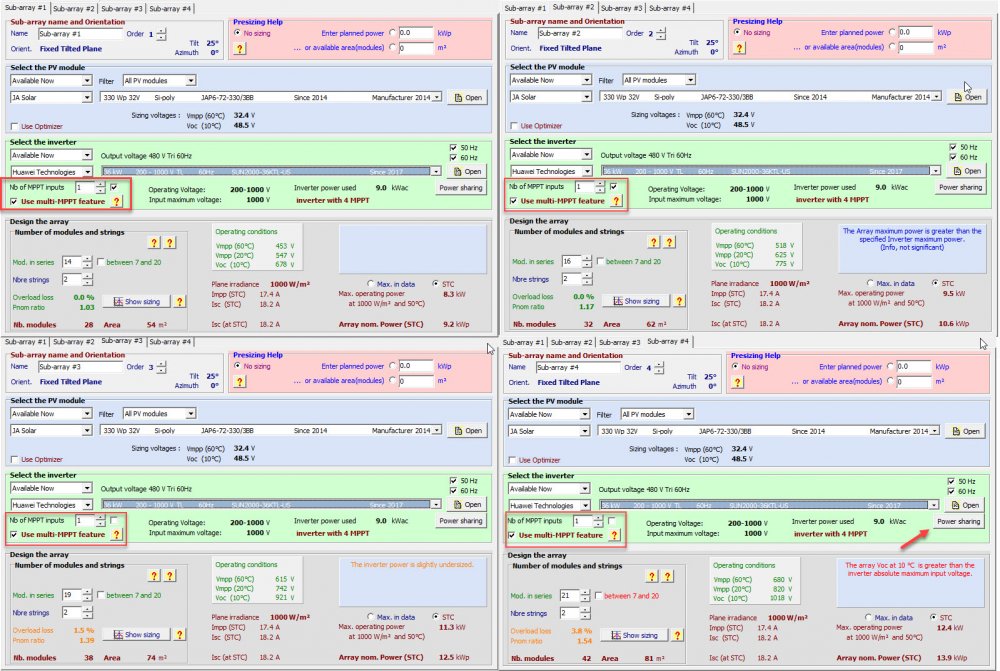
Will the inputs to the inverter be connected together, or operated independently? if independent, you may have higher clipping losses. Some string inverters have jumpers which connect the inputs together, and typically will lower your clipping losses in these unbalanced scenarios. Photo 1 shows the configuration to use to model your scenario, however a string size of 21 seems too high for a 1000V inverter, but your location is not known, so I cant say for certain.


