-
Posts
890 -
Joined
-
Last visited
Everything posted by dtarin
-
Correct, azimuth does change. If the "update orientation parameters" function is part of the process, it would update each of these parameters for each run and be able to execute is my guess/suggestion.
-
Here is another example of the PVsyst report giving different results than expected. Am I going about this the wrong way? Any help is appreciated. https://i.imgur.com/LRgv2RC.jpg
-

How does "Irradiance optimization" option works in Pvsyst 6.7.9
dtarin replied to PAVANAELPULA's topic in Simulations
I am also interested in knowing more about this and where it originated from, how it works, etc. -

Batch Simulation - Error: No Parameters Were Changed
dtarin replied to asboulton's topic in Problems / Bugs
Did you ever resolve this? -
Hello, How does PVsyst determine the Shed spacing value on the PVsyst report? When I have a shade scene with varying row spacings, there is a single value displayed. I did a test with a simple block and three rows, and found that it is not an average. The value displayed changed depending on where I placed the modules (relative to the X axis), which doesnt immediately make sense to me as to what PVsyst is doing. See photo for what I mean by that. Appreciate any info you can provide. The left and right shade scenes were modeled separately. The shorter pitch is 20m, and the larger pitch is 30m. Average pitch should be 25m. Energy is the same, I just need to know if this value shown on the report for more complex sites where there is a greater degree of variation in pitch between multiple rows can be useful in some way. https://i.imgur.com/Gjxe0yD.jpg
-
The bifacial calculation presently only uses the unlimited sheds method (in the bifacial settings), but I believe this will change in the future. The use of a 3D shade scene is for shading loss calculations, and is more accurate than the unlimited sheds method (whether it's bifacial or not). It also allows you to include nearby shading object such as trees or poles if present on your site.
-
Hello, When using module layout in 6.79, the filling method is not filling strings in order. When defining the fill method as "string on one row", in a 4x6 table configuration, PVsyst is using the first six modules of the first four strings to fill the first table, and when moving to the next table, it is not using the remaining modules from the first four strings to continue filling. It is using modules from the next 4 strings, instead of completing the first four strings. The end result is strings are disconnected and very remote from one another. Whether distributing all or manually distributing one table at a time, it is not possible to string such that three tables make one string in length and four in height. https://lh3.googleusercontent.com/nscW8olL8Z6jidpsI1ro9iLqoym2Xx_-67PW5NUpKBGGBJUXb4ozXukQE1FsKmAxnhZlLzDjfU4uENo7X1pOdvdDVUTkMCqIKINRm9MVgVeTUT58Yhavpv0kADTN9hN6qALlXsFms7yRJl_1h0zbXhqhdAb-_rHMesjaWf2VsvXxK9vo_RsVRFiZCT1ViGMZfcG5LZhSuPZv0KpDA4LD6XQnn_dQMTMZDuyzIAFWaKhCz-Z1-WgWohjox4X87-Cl9Q6l-avvVkA1MoNsAQhcFKlRHYS6oPdFWJyRzhm8yY5u56rVIqoOT9wey7V2b1QuuT7aKSKJjaedQCLsfH3xzRZsZlwzcNwLbJ238YlKc5iL_pp8azIhM5Y51zKrvO64VTHPn976Ob9r2-CFuAAAiQUkSqHYm5BipL2qr0vdJ3S4NlQuKOP7S4QzL0Y_MIgVJ-P9xtihPIdQIwNV2MSn09IYjS5J4paWRTqVtAW3NyIHvfziT8PSokLD1KH4w6B9njYQP7_utKPhGwTMxL5l5QOAy9_0riZCABrge147jD3tD7bItfibYgU75ZKjHSW-AJgNPrM0-yIej6mxFP10uzlHYkFyxukgqiIHPIVAAl8x6xSjnrmBEsJtgw1VuUP8Y5Z-GeWsCmlAzFu4-dkuGHhkiDUVNg=w1137-h582-no
-
Does PVsyst have any plans to allow the linking of smaller partitions to create a full partition? Such as when modeling with 4Hx6L tables, three of them will count as one string in length (if defined that way)?
-
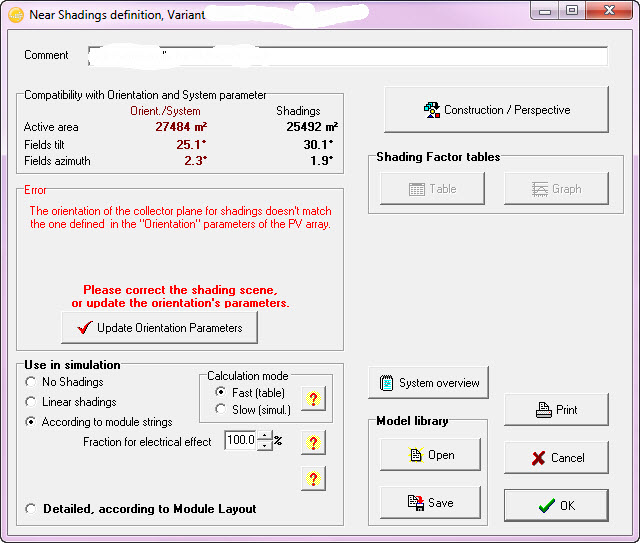
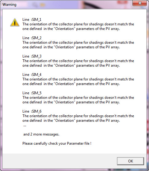
Hello, PVsyst is unable to batch process the tilt variable when ground terrain is incorporated. It seems that what PVsyst is doing is when a tilt is selected, it adjusts the tilt of the tables in the shade scene, and in the orientations section, to the input value on the batch parameters file. However when ground terrain is included, the tables, when set to a given tilt, do not add end up at that tilt; it may be 25.1 degrees instead of 25 degrees. The error shown states "orientation", so this may include both the effective tilt and azimuth calculated in the shade scene with terrain. It would be ideal if PVsyst, in the batch simulation process, took not the value(s) entered by the user in the batch parameters file directly for the orientation input, but instead the effective orientation (tilt/azimuth) from the shade scene, which is calculated after all tables are set to a specific tilt/azimuth (given in the batch parameters file), and used that for the orientation parameter, so that the shade scene orientation and that entered in the orientations section matched. For bifacial simulations, it would be necessary to have this updated as well based on the result from the shade scene. Perhaps more simply, the "update orientation parameters" step is missing from the batch simulation procedure (see second image)
-
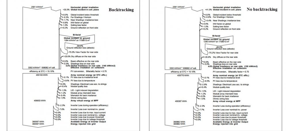
1. Yes. Yes. 2. Select tracking tilted or horiz. N-S axis option under orientation. Under system, select bifacial system above the pan file and select use unlimited trackers for 2D-model. Enter your inputs. Define system (inverters, strings, etc). Go to near shadings, construct a tracker block which matches your orientation settings (tilt if any, tracking range, backtracking/no backtracking). Ensure the tracker block matches your design in terms of module orientation, width, pitch, and representative length of 1 or more strings. Define your partition. Save, exit. Select according to module strings under near shadings. Go back to the bifacial system settings and ensure your inputs match the shade scene: pitch, width, tracking range, etc. 3. The waterfall should be calculated sequentially. In addition, the numbers are rounded (only showing one decimal place). You are not likely able to reproduce the result based on the waterfall. When calculated sequentially I get 367,533.5 (backtracking report), which is due to the rounding of losses in the waterfall.
-
In NA, backtracking with bifacial yields higher than non backtracking I believe in most cases I've seen (c-Si module). I did a test on a site of mine in Southern US; backtracking was 1% higher in total energy than non backtracking. Near shading loss on a 39% GCR without backtracking was ~6%. In seeing your high irradiance, I picked a different location (Chile) with similar yearly GHI, and this trend was also present for this region. 39% GCR, one module in landscape, using the 3D shade scene for calculations and not unlimited sheds. This trend would be the same for monofacial. I would suggest building out your model in the 3D shade scene and ensure your inputs are correct and the same for both models (pitch, etc).
-
Did you model with the unlimited sheds method in the Orientation menu? The electrical effect loss is not shown in the backtracking version's waterfall. I would double check you have modeled shadings properly for both cases. Even when electrical loss is zero, it still displays in the waterfall in v6.78. Either using the unlimited sheds method, or constructing a shade scene and using the "according to module strings" option (more accurate method). These two statements are in agreement and say the same thing. Backtracking reduces POA and lowers shading losses. The reports confirm this. "Total irradiance received" = global incident in collector plane. Make sure you have properly modeled these with regards to shading. If you have a very low GCR, it is possible your shading losses without backtracking are such that the POA gain is higher than the shading loss incurred. Location may be a factor, you have very high irradiance; might be something unique to your location.
-
I would think so. It 'd be ideal if the option in the bifacial option syncd with what is selected in orientation parameters/shade scene.
-
My guess is that one is for the shading loss and transposition calculations, etc, and the one located in the bifacial section is for the bifacial calculation. Checking all, one, or none in that case would give you a different result in each of the three scenarios.
-
Hello, It would be helpful if PVsyst were to permit the simulation of a non-uniform pitch in the shade scene with a bifacial system. Perhaps it could compute an average pitch, or the user could enter a single pitch for the bi-facial calculation.
-
Interested in hearing feedback on this.
-
How did you define your partitions? It's possible that the pole shading is not significant, and with backtracking, results in approx. 0%. In the winter time, module loss according to strings is probably low, and when weighted with the rest of the year, does not result in noticeable losses. When I do a test, I get .001% elec effect losses.
-
I also have this issue.
-
Hello, Presently when entering module X and Y spacing, PVsyst takes N modules (X or Y) times the spacing and adds it to either width or length. Should this be N-1 modules times the spacing, and then added? This would present a method which allows PVsyst to match construction design drawings.
-
Hello, It would be useful to allow the electrical effect parameter to go above 100%. The purpose would be to tune models where there is disagreement with measured data as it is concerned with shading. In cases where the model under predicts, it would serve to add additional shading related losses appropriately, by keeping the additional losses as a function of site conditions, time of day/year, etc.
-

Importing SolarAnywhere data - "Years considered..." issue.
dtarin replied to Chewka's topic in Meteo data
It is possible to download SolarAnywhere data as a .csv file or as a 'SolarAnywhere' file format, in which the latter would use the SolarAnywhere menu selection in PVsyst. -
Hello, Are there any plans to have zones work with tracker systems? Or some other method to modify tracker designs more easily? Presently it is a very manual process and cumbersome process to work with trackers. It would be useful if a selection tool allowed an array block to be split as selected. For example, a rectangle is drawn encompassing a number of tracker rows, and creates new blocks which remain in place. From these three separate tracker blocks, 9 are created, which allows the quick removal if the middle area in the area needs to be removed during a later design stage (image for reference).
-
Hello, It would be useful if when a table or shed is copied/pasted in a shade scene, it takes the name of the table copied and adds a numerical value which increments by 1 so that each copied table/shed/object has a unique name. Copying/pasting sheds/tables saves time, but when there is an error associated with one, presently it will refer to the name of the table; if copied/pasted, it will have the same name unless a unique name is entered each time, which is time consuming when there are a number of elements copied/pasted. Thanks.
-
Hello, It would be useful to be able to select multiple 3D polygons and edit the height for all simultaneously. Presently, only color can be modified when selecting multiple polygons. Thank you.
-

Importing SolarAnywhere data - "Years considered..." issue.
dtarin replied to Chewka's topic in Meteo data
If you imported the SolarAnywhere file as a .csv, you will use the NREL TMY3 format for import, no modifications needed. Edit: I just tried importing a .csv solaranywhere file using the solaranywhere format and I also received that error, so I would suspect that is also what you are doing.


