-
Posts
889 -
Joined
-
Last visited
Everything posted by dtarin
-
You can download PVGIS data here: https://re.jrc.ec.europa.eu/pvg_tools/en/tools.html
-
Hello PVsyst team, It would be helpful if Power Factor was added as a variable to the batch simulation process. Is it be possible for users to modify row 12 and add a power factor variable here in the mean time? 1 PVsyst simulations Batch mode; 2 Simulation parameters definition; 3 File Created on 19/03/20 11:25; 4 ; 5 Project ;;;PROJECT_NAME.PRJ; 6 Variants based on;;VCZ;VARIANT_NAME; 7 ; 8 Please define the parameters to be varied for each run; 9 Don't modify anything in the column titles !; 10 Only the lines beginning by "SIM_" will be executed; 11 ; 12 Ident;Create hourly;Mod. quality;Simul; 13 ;file;loss;Comment; 14 ;File name;[%];; 15 ;
-
Unlimited sheds can. For one module in landscape, define Nb of strings in the width of one row as 3; but you're likely to get a better result if modeling in 3D shade scene (how much better I cannot say). This would only be true for landscape orientation. If modeling in 3D shade scene, with 1 in landscape, and a string size of 5, your partition size would be 3 in height, 5 in length.
-
Hello, It would be very useful if PVsyst were to allow inverter curtailment specific to each sub-array, such that a single project can contain a system where multiple inverters are curtailed differently.
-
This would be a nice feature and very useful at this time. For your initial issue of having all of your PVsyst files centrally located on a network, have you thought about using DropBox or some other similar app where you keep your teams PVsyst files, instead of your work network? It is pretty fast when your internet connection is decent, and changes to files would be saved pretty quickly. In the event you are without internet connection, they'll update any changes once connected. Copies are stored locally on your machine so there isnt any performance issue when accessing them.
-
-

need to maintain variants while changing meteo and site files
dtarin replied to drew.cates's topic in Shadings and tracking
Yes. Just select a different meteo and site file and re-save the project from within the project you are working in. On the Site line, select the magnifying glass ans search for a new site to open and select new site. It will then load and search for nearby meteo files. Select the one you wish to run, save project, and run. If you are running multiple meteo files, it might be easier to use batch simulations to run them. -
Two hours is not a long run time. You can run for half a day or more if needed. I've run 300 batch runs before. Dont use the PC while it's running and use something relatively up to date.
-
GlobInc is POA irradiance
-
Create the curved surface, import into PVsyst as ground data, drop modules onto the curved surface (under edit > set auto altitude). Use a .csv file with coordinates X, Y, Z (in meters) which define your surface.
-
It may not be supported on your version of PVsyst anymore.
-

Issue with shading model during batch simulations
dtarin replied to asboulton's topic in Problems / Bugs
-

Import Near shadings from Helios3D with trackers
dtarin replied to Eric's topic in Shadings and tracking
Last comment regarding helios 3d and trackers from PVsyst: https://forum.pvsyst.com/viewtopic.php?f=24&t=4188&p=9810&hilit=helios+3d+trackers#p9810 -
Not really. You can copy the first page and paste into excel as image (need to resize), or save pdf, and convert to excel. With Adobe it converts pretty well.
-

Can't simulate mixed orient sub-arrays by optimizer and 3D model
dtarin replied to norin's topic in Shadings and tracking
What is the equipment you are using? -
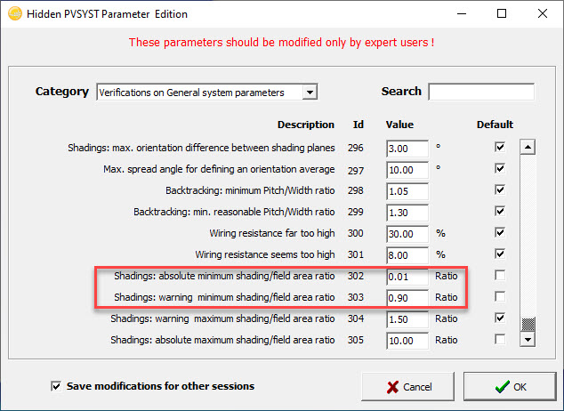
I just simulated with module layout using 1.25MWDC. I got a warning but I just pressed ok and proceeded. Check these settings. The first setting is just an warning. The second setting is for error. This is in Hidden Parameters > System Design Parameters, Losses, Shadings
-

Change to realist view in the final report.
dtarin replied to Michael Velasquez's topic in Simulations
This has already been answered in your other post. https://forum.pvsyst.com/viewtopic.php?f=3&t=4663 -
I believe it sets the number of inverters to a default according to settings when DC AC ratio exceeds something. It will set the number of inverters to get rid of any warning you might have regarding DC AC ratio. I'm not too familar with the use nominal power option, I dont see that on the inverters I use. I check set Pnom ratios the same when inputs in the inverter are shared (jumpered). If your inverter is not configured this way (each input is independent), you would not set it.
-
That is generally true during optimizations. Higher tilt will result in higher shading losses. The other factor to take into account is snow losses if your site experiences snow, as a higher tilt will result in lower snow losses. But in general, yes, you will see shading losses outweigh the irradiance gain from increasing the tilt, although I wouldnt rely on the PVsyst optimization, and actually run the simulation at the different tilts to find exact result. The optimizations can be a good starting point for analysis.
-
There are more variables to consider on a site specific basis, and when comparing different locations. If you are looking at a single site, and comparing changes in GHI year to year, a decrease in GHI may correlate to an increase in diffuse, lower temperature, etc, which depending on system and equipment, may not give the relationship you've calculated. It also depends on system design. High DC AC ratio site may not give the same result, shading losses may be different, etc. So, not quite, at least we don't, due to the uniqueness of each project.
-
Use MPPT share. When you select MPPT share, it will go by the number of MPPT inputs, not inverters, so total you will have 18 (for each inverter).
-
0-9, A-Z from what I've seen, so 36? Never tested it though.


