Search the Community
Showing results for tags '3d scene'.
Found 8 results
-
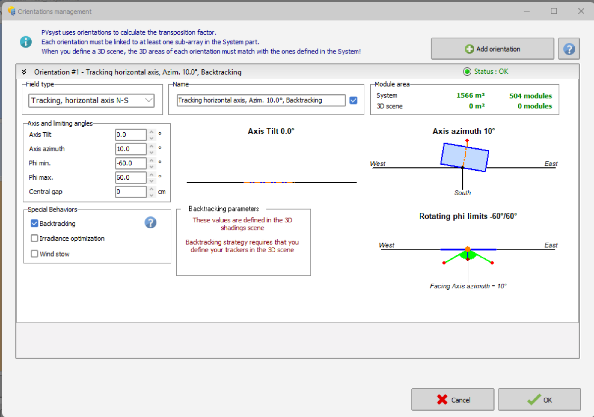
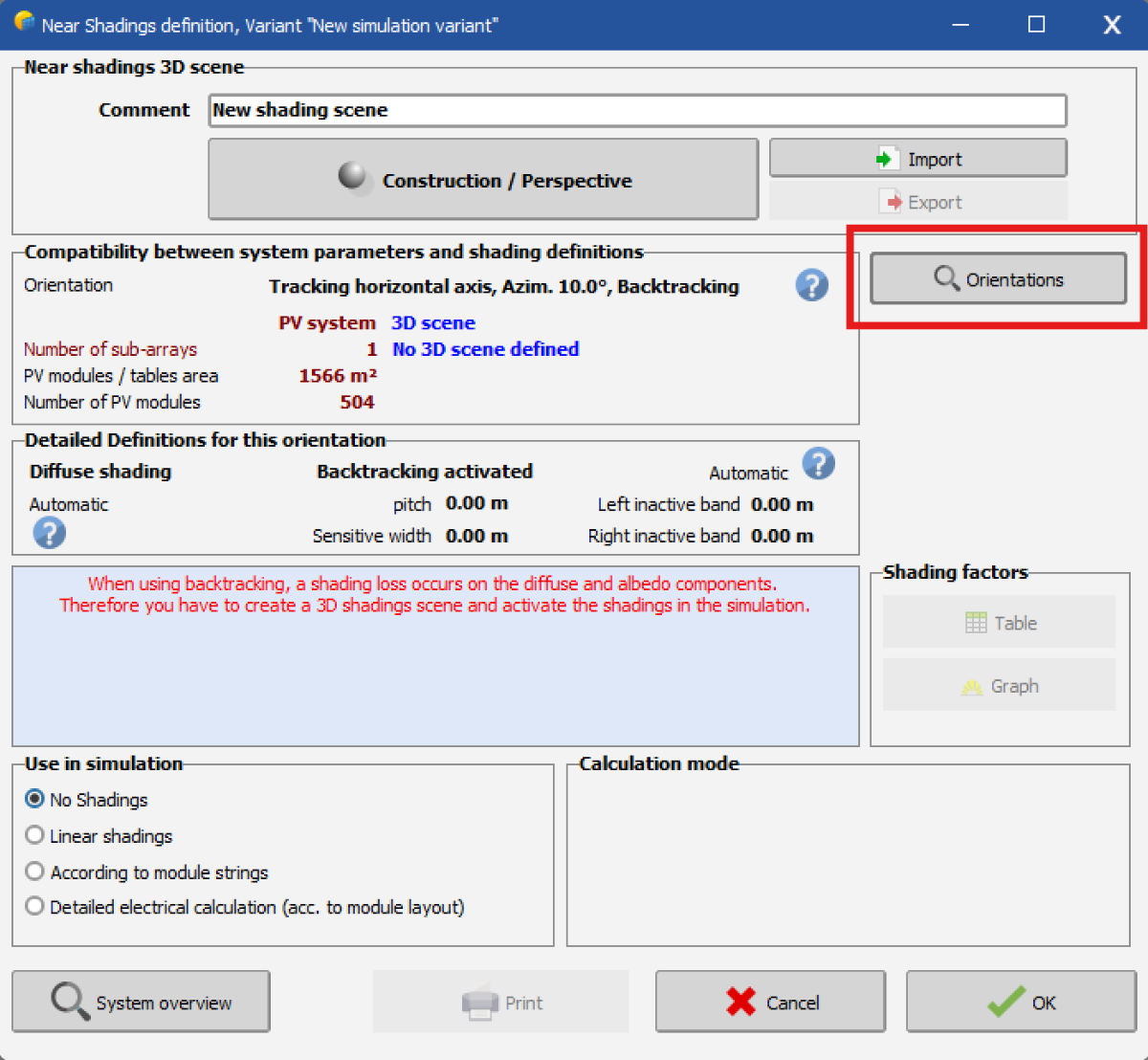
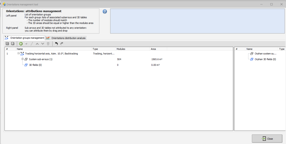
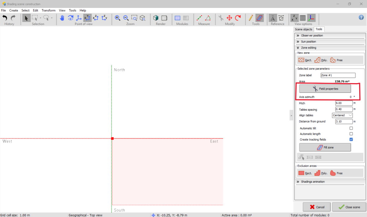
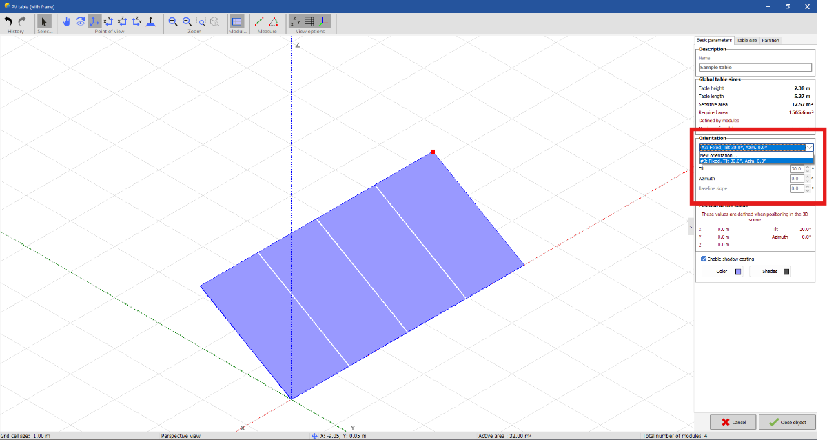
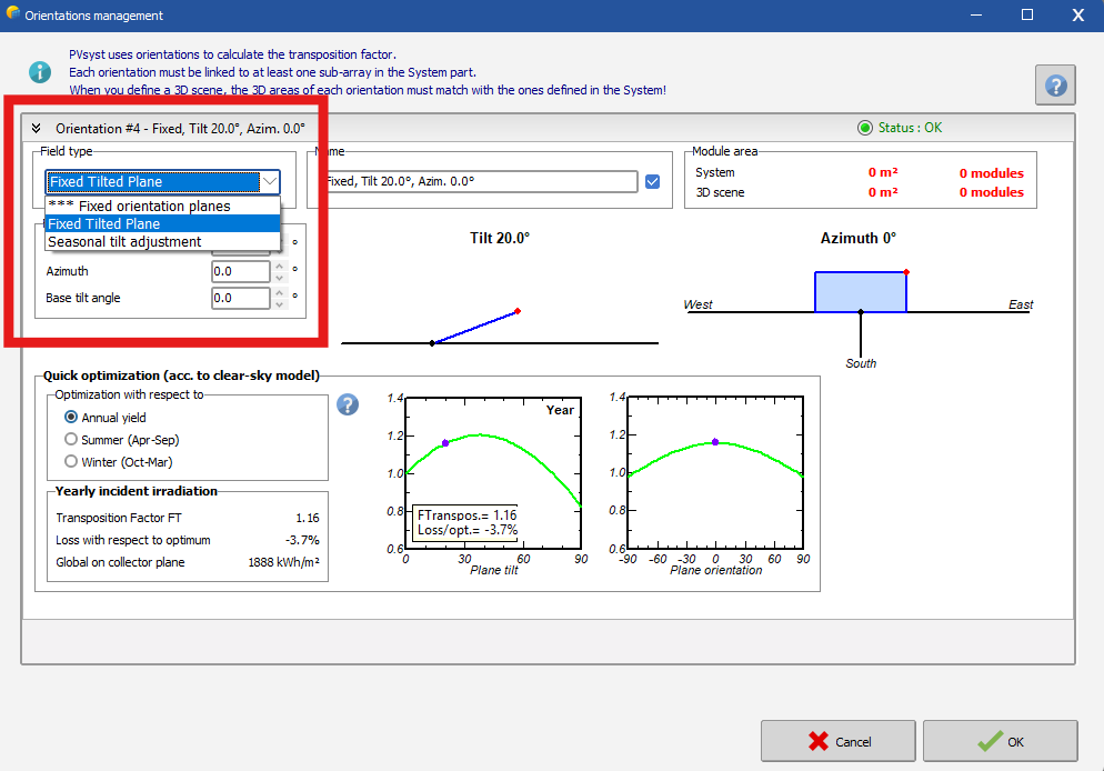
 Hello, I'm having trouble with the "Orientation" objects in PVSyst 8. In the Orientation page I've created a Tracking horizontal axis N-S item with Backtracking activated (see image 1). This orientation is correctly displayed both in the "Orientations" menu of the Near shading 3D scene (see image 2) and in the Orientation management tool within the 3D scene "Construction and perspective" environment (see image 3). However, when I create a new zone in the 3D scene and I click on "Field properties" (see image 4) --> "Basic parameters", I do not see the Orientation I've defined but only a Fixed, Tilt=30°, Azim=0° orientation I've not created (see image 5). Furthermore, if I click on "New orientation..." I'm unable to define any Orientation other than "Fixed Tilted Plane" or "Seasonal tilt adjustement" (see image 6). Any help would be greatly appreciated.
-
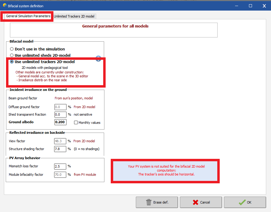
Hello, We are trying to model single axis trackers on different slopes: - from +5 to -5 degrees N-S - from +5 to -5 degrees E-W The 'axis tilt' value for trackers can be changed to model N-S slopes in an array of trackers in the 3D scene. However, when we do a message appears saying "tracker axis must be horizonal for PVsyst to model the bifacial gain". Is there no way around this currently? Secondly, there doesn't seem to be a method of inputting a E-W (tracker to tracker) slope for the array of trackers. Please could you point me in the right direction if there is a way of doing this? Kind regards, James.
-
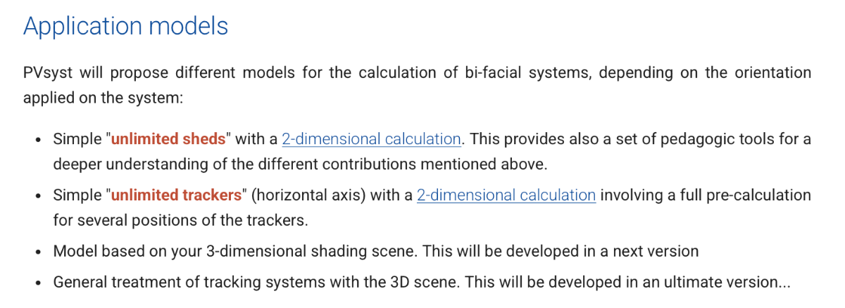
Hi, for bifacial systems, is it possible to use Unlimited Sheds in the 3D scene? Also, when I use Fixed Tilt, I get results very similar to monofacial systems. Does this mean Fixed Tilt is not suitable for bifacial systems? The information provided suggests using Unlimited Sheds or trackers-does that mean Fixed Tilt doesn't properly account for bifacial gains?
-
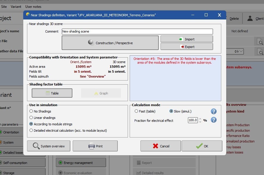
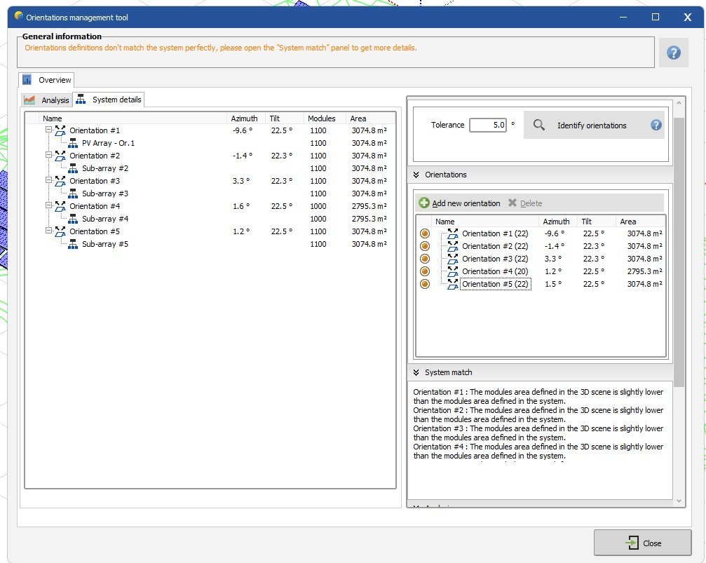
Hi everyone. I'm simulating the terrain in PVSyst. I divided the system into 5 sub-array orientations. In 'Main Parameters>System' I correctly correlated the number of modules for each Orientation with the number of modules in the 3D scene. However, even if the number of modules is correctly listed, the message is displayed as shown in the image below. I am unable to continue with the simulation. I already increased the area of the 3D scene and it didn't work.
-
 Hey PVsyst Team, I have created a CAD file and a .PVC file using PVcase, where my trackers and trees follow the terrain of a specific geography. However, when I try to import the .PVC file into PVsyst, I receive a message stating, 'Your 3D scene is too large and cannot be imported.' Interestingly, the same scene is successfully imported when I remove some of the trees.
 -
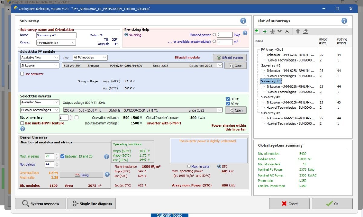
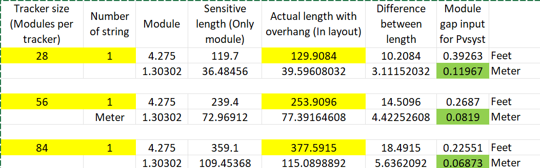
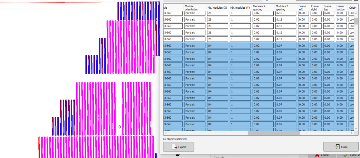
When PVcase exported PVC file imported into PVsyst, the tracker has more number of modules than it should be (87 modules per tracker instead of 84 modules ). I know this is due to the tracker motor gap and foundation gap for terrain following trackers (Multiple bays of 7 and 8 modules with foundation gap). I tried to divide all the gaps into module spacing to achieve the tracker length and changed the number of modules per tracker to actual numbers. See spreadsheet screen shot. In the process, I modified the rectangle’s length to equal the number of modules per string times the module width. However, this adjustment reverts to the original incorrect lengths when applied to trackers with different string configurations (2-string or single-string), showing 87 modules for a 3-string tracker instead of the correct 84. As a workaround, I’ve manually selected all similar trackers and altered the module numbers using the CTRL+G command. Question is- 1. Is this the correct method? If not, do we have other methods for simulations of terrain-following trackers with multiple bays? 2. Does this affect the thermal losses as modules have larger spacing compared to actual spacing (1 inch for reference)
-
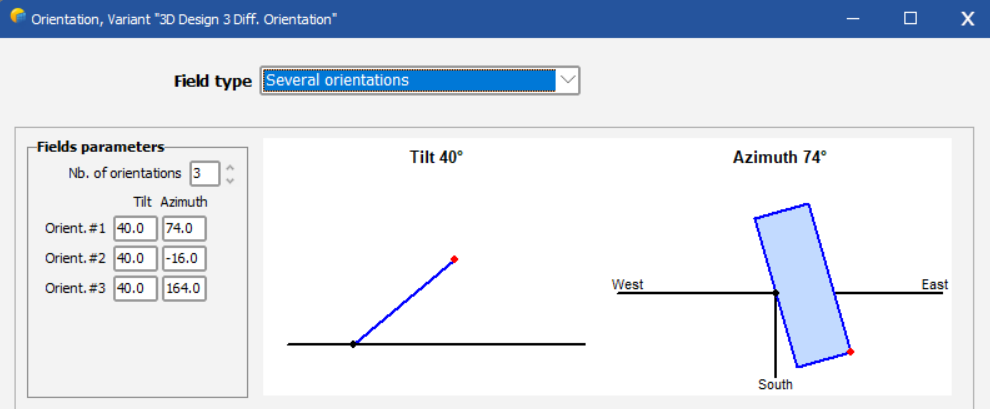
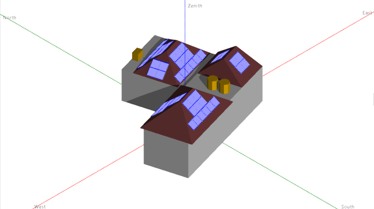
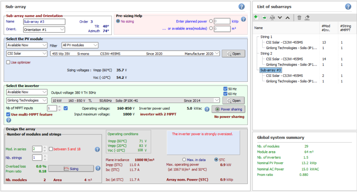
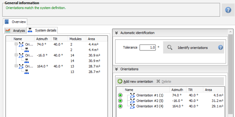
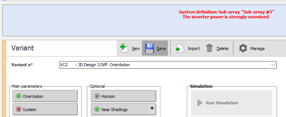
Hi all, I'm currently having problem on simulating multi orientation module specifically when creating a near shading 3D scene as it mentioned "The area of the 3D fields is lower than the area of the module defined in the subarrays". I'm not sure if PVsyst didn't allow/unable to simulate for this kind of cases or there's some setting I didn't click on/adjust. My system consist of 3 diff. orientation whereas string 1 facing South & string 2 facing North + West. Under parameter already define with 3 nb of orientations & under subarrays, I only put 2 as if add another subarray specifically for another orientation, PVsyst will detect 1.5 nb of inverters & will cause an error mentioned "The inverter power is strongly oversized". I notice PVsyst detect all 16 module as 1 orientation (string 2) even though on 3D some module already facing diff orientation. Btw this simulation for Residential with below details: Inverter: Solis 3P10K (2 MPPT) Solar Panel: Canadian Solar 455W Nb of module: 29 Module layout: Sub array 1 (13 module) facing South, Sub array 2 (14 + 2 module) facing North + West. Here's another image if I separate all orientation with individual sub array. Hope someone can help on this issue & correct me if there's mistake based on image attached. Thank you!
-
 I cannot simulate tracker's 3D scenes built with AutoCAD and plugings like PVCase or VirtuoSolar. With fix structure I was able to solve it by changing the tolerance in the "shading scene construction > tools > orientation management". Most of the scenes I am building are placed in sites where irregular terrain characteristics having NS tilted trackers with tilt angles from -8Dgr to 8Dgr is very common. In my projects computing 3Dscenes under this scenarios is a must specially because I need to use bifacial modules. PVSyst 7.2.12 Screen shoots How can I process this type of 3D scenes ? What I am doing wrong ? Thanks and regards M