
dtarin
-
Posts
897 -
Joined
-
Last visited
Everything posted by dtarin
-
US-based designs are in ft, yet the pitch input is in meters and only to two significant figures, resulting in (backtracking-related) issues when converting. Please increase to four decimal places.
-
There is no straightforward answer. Are you modeling tracker or fixed tilt? What is your table size in PVsyst shade scene relative to your string length?
-

simulation with positive value in pv loss and inverter loss
dtarin replied to byat's topic in Problems / Bugs
Your PAN and OND files are not correct. -
I've been getting this often, and PAN/OND files being invalidated
-
There should be a report which accompanies the PAN file that details the IAM calculation. If there is not, I personally wouldn't use it until there is such a report available.
-
For shading calculations by considering very long rows, unlimited sheds ignores edge effects. Modules on the edges of an array will have lower shading losses compared to modules on the interior of an array, which is what unlimited sheds captures. This has a tendency to produce less accurate shading losses compared to generating a 3D shade scene.
-
Temperature yes, if it is specified in the OND file. Voltage, I am not sure.
-
See here. https://forum.pvsyst.com/viewtopic.php?f=23&t=5316
-
You are not required to choose one of the pre-sizing features. Simply select No sizing.
-
Is PVsyst able to determine the tables distance on N-S slopes?
dtarin replied to oliver jr's topic in Shadings and tracking
If you are using PVcase, you can export that shade scene very easily into PVsyst. -
What PVsyst does is it calculates the rear-side irradiance contribution, adds this irradiance gain to the front side irradiance, and then computes the generation using the combined irradiance. The current and energy values reported by PVsyst will consider this total irradiance (rear side + front side). If you would like to find out how the rear irradiance affects current, you can try this: Run a bifacial simulation, output in the 8760 current Run a monofacial simulation for the same variant (just disable bifacial under system, use the same module); output current Compare the current output for each run Voltage seems to also be slightly affected.
-
Hello, It would be helpful if the Check scene validity tool was revamped. Something like a side menu opening up with a list of all items discovered, where the user can select the table/object would be great.
-
Another option is meteonorm. The methodologies are similar. They use a digital elevation model and trace back out from the point of interest, calculating the height of the terrain for various azimuths. I think outside of on-site measurement, both are reliable. I have not seen a validation study, however.
-
-10C is the default minimum site temperature defined in project settings. This needs to be set per your specific location. If -10C is your site minimum temperature, then you need to adjust your string length so your Voc voltage does not exceed the voltage rating of your inverter.
-
You can have them both in the same project by defining two subarrays under system, or you can model them separately in 2 different variants.
-
If you mean power factor, yes, under energy management

-
yes. Use the mppt share function of the inverter. There are many threads on this.
-
probem in reading the hourly parameters from CSV file
dtarin replied to basalama's topic in Problems / Bugs
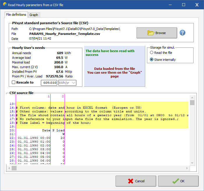
See thread here. https://forum.pvsyst.com/viewtopic.php?f=23&t=5316 Your load profile should be based off the template included in PVsyst. -
Using Bifacial and Monofacial Modules in different Sub arrays
dtarin replied to vijaykrishna.ds's topic in Simulations
Run two models, one with monofacial, one with monofacial set with bifaciality set to zero and compare. -
Yes, it is correct that a 3D shade scene is more representative. The edge refers to the the modules which are along the edges of the array. If you have a square block, it is the first row, top row, left side, and right side. These modules receive less shading, more reflected irradiance, etc, and hence more energy.
-
I urgently need help with PVsyst! Uni dissertation submission in 5 days
dtarin replied to omairahm's topic in Simulations
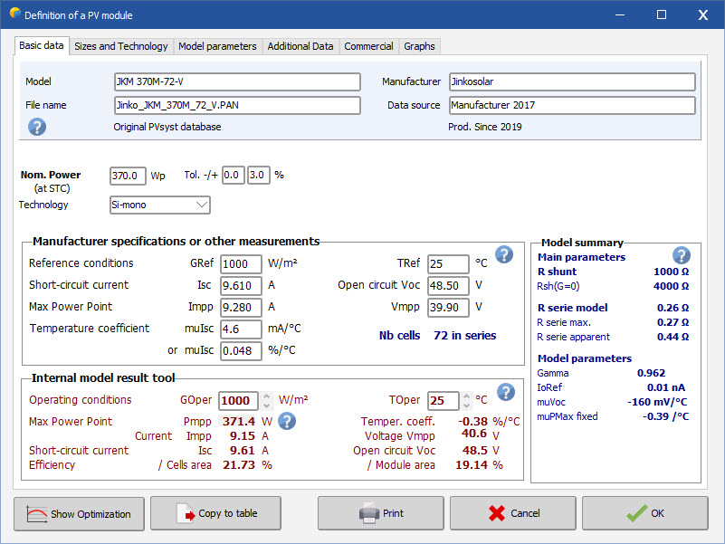
Check your PAN file. Your Vmp value does not seem correct, it is too high. For a 1500V system, you should be in the mid to high 20's for string length. You also want a higher DC/AC ratio, 1.2 to 1.3 good range. I suggest getting a new PAN file, or double checking the IV characteristics against the datasheet.
-
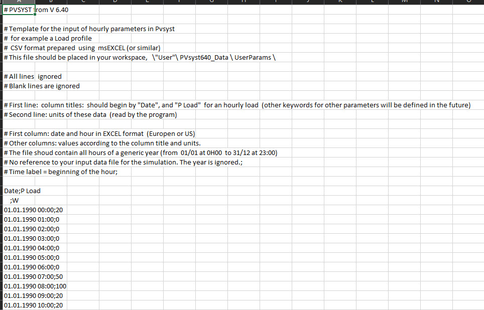
Find this template, and populate it with your data. The template is located here: C:\Program Files\PVsyst7.1\DataRO\PVsyst7.0_Data\Templates (or whichever version you are using). The template filename is PARAMS_Hourly_Parameter_Template.csv. This is what it looks like after loading the template file.
-
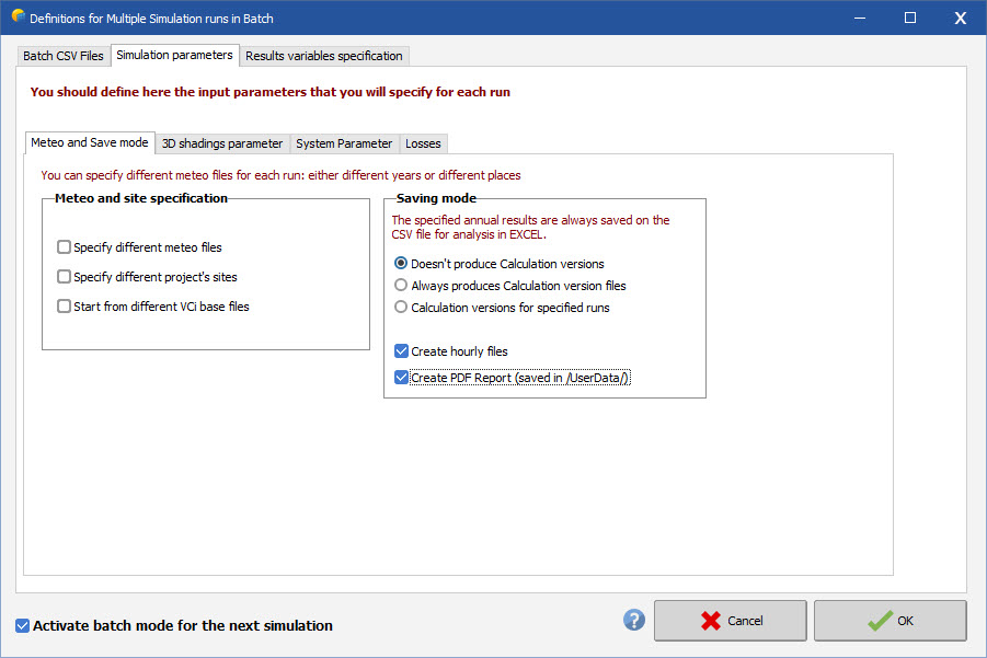
Once you're ready to simulate, click advanced simul. menu, select output file, check filename so that a 8760 file will be generated, press ok. click batch simulation, check the box create hourly files, and create pdf report; verify your variable under test, and the output variables under results variables specification, press okay. run simulation. 8760 files will be in /UserHourly, PDF files will be in /UserData, BatchParams and BatchResults will be in /UserBatch
-
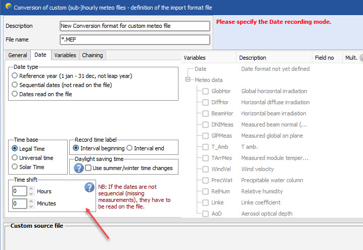
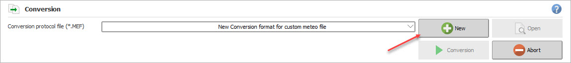
When importing a custom weather file, create a new conversion format based on your data file. There is a place to update the time shift. You will need to import the meteo file first each time to see the time shift, and then go back and adjust in the conversion format as shown. If you want to upload the excel file for your data as a template, I can create a conversion format file for you. Just fill in all of the data with 1's, leave the headers, date, and other formatting as is.
-
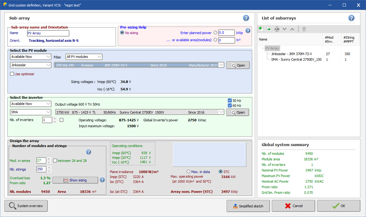
Disable mppt share. Set to 14 modules in series, 30 strings.