
dtarin
-
Posts
897 -
Joined
-
Last visited
Everything posted by dtarin
-
 Inverter loss over nominal power is the same as inverter clipping. PVsyst handles clipping losses appropriately in my experience. It is difficult to say what is occurring without knowing some other details like which inverter or where the project is located (temperature, yearly GHI, etc). A 1.4 ratio seems a bit high to only have 0.3%, but it will be dependent on system type (ground mount, tracker, rooftop, etc.), equipment, and location.
 -
Lead acid or lithium ion are the two most common I believe.
-
Bi-Facial Module electrical characteristic with % gain
dtarin replied to Tokoyoshi's topic in PV Components
There is no single frame of reference to define bifacial gain. You can look at the irradiance gain after bifaciality and consider that. Or you can look at the the output at the inverter terminals with and without bifacial included, as you have. One might compare a monofacial module to a bifacial, as there are physical (and economic) differences between the two. Using irradiance after bifaciality is common in my experience. -
Bi-Facial Module electrical characteristic with % gain
dtarin replied to Tokoyoshi's topic in PV Components
You are comparing an irradiance gain with an energy gain. The two are not the same, nor will ever be. It is typical to have a higher irradiance gain than your MWh gain as there is conversion still from light to electricity and other downstream losses than can be influenced (i.e. clipping). -
Where can I find PV-syst ready solar data from the last 10 years?
dtarin replied to S Groenveld's topic in Meteo data
SolarGIS, SolarAnywhere, or any of the other satellite based providers (not free) or NREL PSM (free, not sure if it's been updated but tends to overestimate GHI). -
Try creating a net with the handrail object. Set width of rail to whatever the thickness is, and the number of vertical rails to the spacing of the net, and place in the front of your fixed tilt system oriented normally. Then run a simulation with and without, take the delta, and add to rear shading. I tried running this with a 4x7 table and a large "net" structure with thin object shading set to 5%, but after running for hours it crashed. Perhaps a single module will be more successful.
-
"Slide rows" button in Zone editing tool causes soft. to freeze
dtarin replied to julmou's topic in Shadings and tracking
Try to include the version you are using whenever posting on an issue. I have tested in 7.2.14 with no issues, whether automatic length on or off. The blue band that appears when you activate the slide tool stays on the screen however after I use it. When I close the zone menu it goes away, but when zone is active again, it comes back. Maybe a bug with the tool, as I have not encountered this in prior versions. You can still slide them by deactivating zone and using the standard crosshair tool. -
Grid power limitation - KVA profile instead of constant value
dtarin replied to jay9098's topic in Simulations
Or alternatively, run however many different PVsysts there are for each scenario, then splice them into one 8760. -
Grid power limitation - KVA profile instead of constant value
dtarin replied to jay9098's topic in Simulations
Export to excel to accomplish this for the time being. -
Is this calculated as a weighted average?
-
You might be able to accomplish this using batch runs. You cannot do this on an hourly basis, but on a yearly basis and then assemble the results as you wish.
-
Project Settings > lowest temperature for "warm" countries
dtarin replied to julmou's topic in Simulations
One year of data is not sufficient to establish what an outlier condition is (what if it is warm that year?), nor would TMY data be sufficient. A TMY (synthetic or based on time-series) contains "typical" values, and not what you are looking for when designing a system to protect against damage in the rare situation where you have both low temperatures and sufficient irradiance. Ideally you want a few decades of temperature data. I've provided one resource which gives you several different timespans containing the low temperatures. I am not sure if NREL or NOAA has data for AUS, but there might be some public source for weather data similar to what we have in the US. -
Create an inverter with dummy MPPTs and allocate strings accordingly for each module type to one shared inverter. It looks like there you have two inverters which have two types of modules connected to it, but hard to read the small print in the screenshot.
-
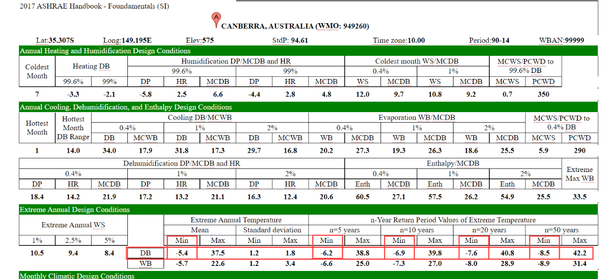
Project Settings > lowest temperature for "warm" countries
dtarin replied to julmou's topic in Simulations
Here is one reference. Select from here temperatures under the "extreme annual design conditions". From there, it is up to the designer to select. They generally go from least to most conservative starting with the mean on down towards n=50 years. I personally wouldn't select the mean or n=50, however. I usually go with the 10 or 20 year minimum depending on other factors. http://ashrae-meteo.info/v2.0/
-
I was able to edit, click the three dots, edit button is there, works fine. ::Edit::
-
IAM is automatically included using plain glass fresnel option. They are reviewing whether to include this as a separate loss factor so as to be able to determine rear POA before all loss considerations.
-
Unlimited sheds in PVsyst for PV power plant
dtarin replied to Mohamed's topic in Shadings and tracking
If you are using unlimited sheds, the exact number of rows does not really matter. Enter 100 for large utility scale plants. -
When re-running a project (initially created in 7.2.6) in 7.2.14 using the fast simulation method, the near shading losses are 0.34% lower (tracker site in Maryland, USA). Can PVsyst provide any information on where the change might have occurred with some context? I have found the following in the release notes. 0.34% for a utility scale project is not a small number. Without being able to parallel install subversions, it is difficult for users to properly track changes to production due to changes in the software, and continues to be a problem. As such, I cannot run detailed comparisons with full variable export in 8760 without having to now uninstall and downgrade to 7.2.6, then reinstall back to 7.2.14. 7.2.10 - Shadings: a small diffuse shadings correction was added for negative tilts. 7.2.12 - Simulation of trackers: irradiance optimization is now taken into account in the calculation of diffuse shading
-
Want to push this request up. When exporting projects for customers or other parties, it is quite cumbersome to have to go and delete various weather files, components, variants, etc. every time.
-
+1 for this feature
-
Are rear IAM losses included when computing the bifacial PR?
-
The purpose would be to allow the inverter to be limited below nameplate power (which is not uncommon), and also allow a grid limitation to be applied at the POI. This is easily implemented in excel, and should also be able to be implemented in PVsyst.
-
When testing, the measurement device(s) is likely to not be directly behind structural elements. If PVsyst can calculate the shading and IAM loss separately, could we not take GlobBak before shading and IAM losses, and use the measured irradiance to replace/correspond to this value? GlobBak = global irradiance on rear after shading and IAM GlobIncBak = global irradiance on rear before shading and IAM In this way for testing, we have a variable that corresponds to something somewhat represented by the measurement apparatus. And in terms of importing that data, PVsyst could then use this new variable to be replaced with measured data.
-
The thin objects in your scene will have the box checked labeling them as a thin object, and the trees will not. The software will calculate shading from cables as a thin object, and trees with the according to strings setting. As for what % to use, different folks will provide different answers. It is dependent on the technology, the nature of the tree shading, how modules are installed relative to the shading, etc. Typically it will be between 70% and 100% for according to strings. Most of the time I am modeling with 100% so as not to underestimate shading losses.
-
Any graphics driver updates recently?