
dtarin
-
Posts
897 -
Joined
-
Last visited
Everything posted by dtarin
-
To my knowledge, PVsyst cannot run a meteo file which is longer than a year. So regardless of how you approach, it will split them up or you will manually. Convert the format of your CSV into the PVsyst standard you linked. Here is screenshot of what I did, it worked fine and created 23 MET files. You may need to adjust the hour shift or time shift (in minutes) depending on your location.

-
It can import monthly data, it does not have to be a full year, and it will create hourly average. Screenshot below for a single month of 1-minute imported data.
-
You can import 15 minute data and pvsyst will convert to hourly
-
-
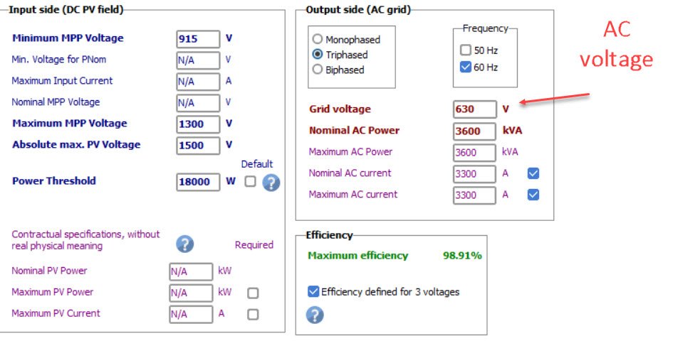
You wont be able to find DC voltage in the OND file, it comes from your PV system and is dependent on other factors. You will need DC voltage from the 8760 data. AC voltage is stated in the OND file.
-

How to import obstacles into the 3D module layout.
dtarin replied to sujinlee's topic in Shadings and tracking
Go to create > elementary shading object. Wind turbines are available, as are other objects. If you need something specific, you can either build it piece by piece or use an approximate shape.
-
I did find a bug, though, @Michele Oliosi. If I delete the orientation, select add new, I get an empty orientation. Double click, add fields, select all tables, and whether I click close or switch back over to the overview tab, the modules do no allocate to then new orientation, it stays at 0/0/0. It seems the only way to add tables to the orientation is to use the identify orientations button (doesnt allow custom allocation), or by right clicking on the empty orientation.
-
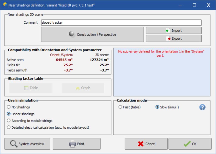
your screenshot shows 0 tilt, 0 azimuth, and 0module area. i am assuming there is an issue with your pvc import, or you dont have any modules assigned from within the shade scene. go in and allocate tables to that orientation if possible. module image for reference
-
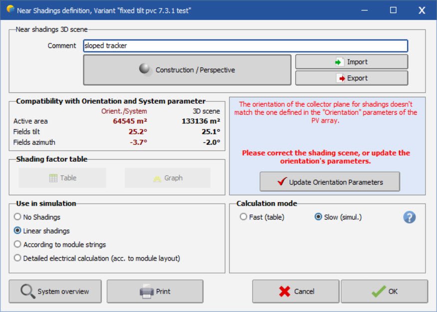
I tested this in 7.3.1 and it worked fine for me. I imported a pvc file I set tolerance to 20, then identified Since I was starting with a tracker variant, i got this message. i went into system, changed to bifacial fixed tilt, then it worked fine. I then imported a different pvc scene for fixed tilt while fixed tilt was already selected under orientation menu (instead of starting from tracker variant). it showed 8 orientations, i changed degree tolerance to 20, then identified new single orientation. this is similar to your message i clicked close anyways with that message and got this message like i showed before then pressed update orientation parameters and it worked fine
-
-
Did you save and exit the shading scene? There is often a dialog that appears to require the user to resolve the discrepancy between shading scene changes and the initial orientation.
-
The auto altitude function works for fixed tilt systems, but does not adjust the tilt for trackers. There is an automatic tilt function available when creating a zone of trackers, but if the tables are already created, there is no way to adapt their tilt to the terrain, only their elevation. It would be great to add this feature.
-
The number of transformers doesnt really matter in PVsyst, it will create a single transformer for the transformer loss calculation. For ohmic losses, calculate the total weighted average power loss for the entire system and use that for the medium voltage line input. From your previous post, if the total power loss of both circuits is 0.60%, that is what you will enter for loss fraction at stc (assuming that value was calculated at stc conditions). Regarding your previous post , the average loss would not be 0.1% for each transformer. In each circuit, each "leg" is carrying a different current value. The first leg is 1/3, the second is 2/3, and the last leg is 3/3.
-
Certain software can export PVC files - PVcase (autocad), pvDesign, helios 3D, to name a few.
-
-
What I described will accomplish this.
-
Nb. of modules in width (unlimited sheds)
dtarin replied to Gonzalo Piedra Mendoza's topic in How-to
Inactive band does not refer to module spacing; module spacing is a separate entry in pvsyst. Inactive band refers to a physical structure extending out past the modules which will cast shadows. -
You can import ground terrain in a number of ways, or you can create an object which slopes in the directions you want, and then drop the trackers on top. It will depend on what you're currently working with and what the purpose is. For example, you can create a large house for a very simplistic and uniform E-W slope and select the modules for each side and drop onto each half of the house using Edit > Set Auto Altitude. The tilt for each side of the roof can be easily set from within the block settings.
-
Nb. of modules in width (unlimited sheds)
dtarin replied to Gonzalo Piedra Mendoza's topic in How-to
In a fixed-tilt system, it is related to the number of vertical modules, and defines how many electrical partitions you have in the vertical direction. This determines the electrical effect losses due to shading. Inactive bands are typically set to zero; this refers to a support structure which extends past the module. -
If tilt is zero, you dont need to consider mixed orientations. Just create two subarrays, each with 2 inverters, and the number of modules/strings per roof for each.
-
Also, when using PVC files or you have any shade scene where individual tracker rows are being modeled, you will need to use the backtracking management option and select a representative pair.
-
Shading will be accounted for, and will reflect the different heights and tilts for calculating shading. In terms of tilt, the POA irradiance will be adjusted depending on the average tilt of the shade scene. This is done automatically by the software.
-
Use total module length. This is standard practice
-
Same OND files? Is one using MPPT share and the other not? Post screenshots from System menu showing the arrays for each.
-
DC Voltage drop losses value with Bifacial Modules
dtarin replied to Sergio Alonso's topic in Simulations
Ohmic loss inputs in PVsyst are up to the user to define, so you should be considering the current under bifacial conditions when sizing your cabling and determining voltage drops, etc. PVsyst will consider the hourly I^2 x R losses inclusive of bifacial gain, but this is not determining what the initial input is, that is determined by the user based on their design.