
Stéphane
-
Posts
76 -
Joined
-
Last visited
Everything posted by Stéphane
-

Unwanted line that generated when importing ground data by .csv
Stéphane replied to Solaranger's topic in Problems / Bugs
Hi, the triangulation tries to connect all dots of the model, hence the lines you see. To get better accuracy you can import points for those areas as well. However since the checkbox "Enable shadow casting" is not checked it will have no impact on the simulation. Ground objects are usually used to properly position the PV panels and they are usually not casting shadows, except in specific cases. So you should be good to go. -
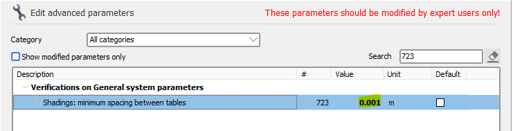
Hello. PVsyst reads the DAE file and import the content of it. You should check the scene in your source software, adjust it (add space between the tables if needed) and regenerate the DAE file to import it again in PVsyst. If you cannot (or don't want to) add more space in your source software or modify the scene in PVsyst, you can modify the following advanced parameter in "Settings > Advanced parameters": If you still encounter issues, you can deactivate those checks from the shadings scene in the menu "Tools" : Please make sure to carrefully read the warning displayed when disabling the check as disbaling it can give incorrect shadings calculation.

-
The axis tilt difference is to high - Tracking system
Stéphane replied to Douglas_L's topic in Problems / Bugs
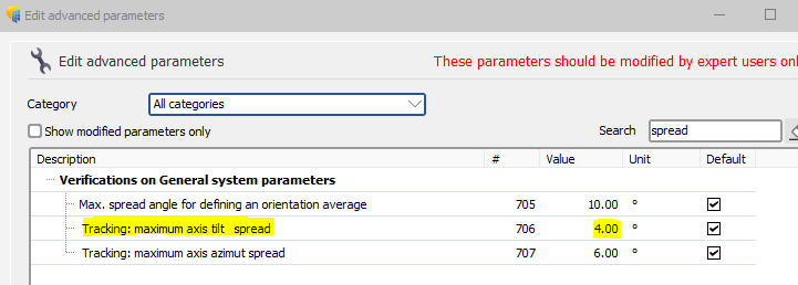
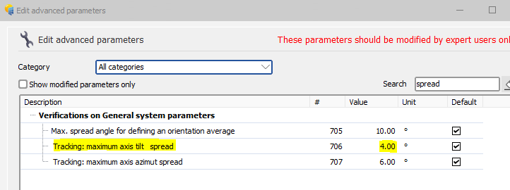
Dear Douglas, To get rid of the error message, you can go to the advanced parameters (menu “Settings > Edit advanced parameters” from PVsyst first window), search for “spread” and modify the following value: Please keep in mind that the default value is 4° so increasing it can lead to results that are not entirely accurate, but at least you will be able to run the simulation.
-
Hello. Perfect, I am glad it is now working for you.
-
Hi, This error is usually displayed when you have one object of your scene that is really really far away from the other ones, making the distance between this object and the other ones too big to handle. Removing this object in your 3D software and exporting a new file will solve the problem. If you cannot solve the issue you can send us your PVC or DAE file to support@pvsyst.com and we will have a look. I hope this helps.
-
pvsyst file from PVCad - Azimuth Issue
Stéphane replied to Shubham Kolpuke's topic in Problems / Bugs
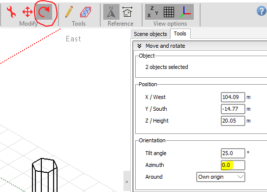
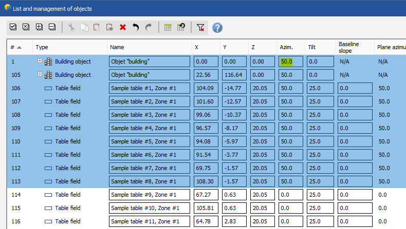
Thank you for the additional information. The SHD file format is designed for PVsyst internal use only. So probably the way it was generated by the external software was not entirely correct. In any case, you can try to rotate objects in PVsyst directly. A first way of doing this by selecting the objects in the 3D scene and then click the rotate button. Then you can change the azimuth: Another way to do it is to click on the menu "Tools > List and management of objects". There you can also change the azimuths of some/all objects at the same time: If this doesn't solve your problem, please send us your SHD file to support@pvsyst.com so that we can have a better look.
-
Hello. I am glad that the workaround worked. The visual issue looks like a zoom issue. You can have a look at this video on how to set the zoom back to 100%. I hope it will solve the issue:
-
Hello, Here is a workaround to click OK. Click with the mouse on "Tree_crown" (the text itself, not the checkbox) then press two times on "Tab" on your keyboard and finally press "Enter" on your keyboard. Regarding the bug itself, I was not able to reproduce it. Are you using the latest version of PVsyst?
-
pvsyst file from PVCad - Azimuth Issue
Stéphane replied to Shubham Kolpuke's topic in Problems / Bugs
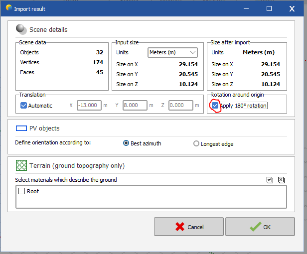
Hi, if you are importing a PVC file or a DAE file, you can apply a 180° rotation by clicking the following checkbox:
-
PVcase PVC export problem with terrain following tracker
Stéphane replied to ShivamPandey's topic in How-to
Hello. Did you check the "Terrain following trackers" checkbox in the "Frame creation" tab in PVcase? This setting should break the PVcase trackers into multiple smaller trackers for PVsyst (according to the defined gaps), placing the modules at the correct location. -
Daily shadow generated by wind turbine
Stéphane replied to AlvaroRuiz's topic in Shadings and tracking
Hi. No this is not something that is currently possible in PVsyst. -
Hi, can you please send us your file by email at support@pvsyst.com so that we can have a look? Thanks in advance.
-
Hello. Unfortunately this is currently not possible in PVsyst. However your scene doesn't look too complex so you might be able to design it from sratch in PVsyst to achieve the desired result.
-
It looks like the total area is matching between the 3D scene and the System window but it does not match for Orientation #2 and #3. If you can't fix it you can send us your project zip file by email to support@pvsyst.com so that we can have a look.
-
near-shading with tracking, without 3D scene
Stéphane replied to S.Faulkner's topic in Shadings and tracking
Hi, PVsyst supports several 3D file formats for import, namely *.DAE; *.3DS; *.H2P; *.PVC. You can find information about these files and the process to import them in our online help: - https://www.pvsyst.com/help/index.html?sketchup.htm - https://www.pvsyst.com/help/index.html?helios_3d.htm - https://www.pvsyst.com/help/pv-collada-file-format.htm The first link above also explains how to convert AutoCAD files to *.DAE file using Sketchup. I hope this helps. -
Hello, From your screenshots it looks like you are measuring the distance between two trackers and not the distance between two modules within the same tracker. If you double click on a tracker it will open its details window. There you can go to the "Trackers sizes" tab and look at the width and length of the sensitive area. Then you just need to add the size of the frame to know the full size of your trackers. I hope this helps.
-
Hello, If you are using domes then you need to create 2 orientations (one east and one west). If you are using trackers, only one orientation is needed. When importing trackers from pvcase PVsyst will try to detect automatically the corresponding orientation. I hope this helps.
-
Hello, PVsyst reports a discrepency between the System window (where you have only 1 subarray with all PV modules attributed to it) and the 3D scene where you have PV tables spread accross multiple orientations. The orientations detected in the 3D scene are likely due to your PV panels following the ground (so having different base slope angles). To fix this you can increase the "Tolerance" in the orientation management tool and click on the "Identify orientations" button. You can increase it until you get only 1 orientation left.
-
You are correct. In the details window of the ground object there is a checkbox called "Enable shadow casting". If it is not checked then the ground object is ignored when calculating the shadings and collisions between the ground object and PV tables have no impact.
-
Hello, Thank you for reaching out. We will improve this feature in one of our upcoming releases. In the meantime, you can increase the "Distance from ground" in the zone editing tool before filling your zone. This should fix your issue. I hope this helps.
-
Hello, In the welcome screen of PVsyst you need to go to menu “Settings > Edit advanced parameters”. Then search for “spread” and modify the following value: Please keep in mind that the default value is 4° so increasing it can lead to results that are not entirely accurate, but at least you will be able to run the simulation. I hope this helps.
-
Hello, We have the notion of central gap in PVsyst but maybe this information is not in the PVC file that you are trying to import. Can you please send us the PVC file by email at support@pvsyst.com ? This way we will check and if the information is missing we will reach out to PVCase to see how we can improve our integration in future versions. Thanks in advance.
-
Hello, In the 3D scene you can create multiple single PV tables or multiple arrays of tables, each with the required tilt. Then you can go to "Tools > Orientations management", increase the value in "Tolerance" and click on the "Identify orientations" button until you get only one average orientation left. Then you can go to the main "System" window and you will be able to use only 1 subarray. I hope this helps.
-
Not able to simulate PVcase export + Bifacial fixed tilt
Stéphane replied to Chirag's topic in Shadings and tracking
Hello, You can have a look at the help section regarding this topic : https://www.pvsyst.com/help/bifacial-conditions.htm If you have modified the correct advanced parameter, I would suggest increasing its value again. If you still encounter issues, you can send us your project files at support@pvsyst.com so we can have a closer look. Regards, Stéphane -
Hello, No unfortunately currently there isn't any easy way to achieve this in PVsyst directly. The best approach would be to design your scene in an external software and then import it into PVsyst. Regards, Stéphane