Search the Community
Showing results for tags 'pvcase'.
Found 7 results
-
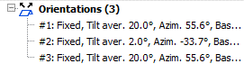
Hello, I am facing an issue with the near shading tool in PVSyst. For the construction/perspective of the near shading 3D scene I am importing a 3D pvc file as generated in AutoCad using PVCase GroundMount. In my AutoCAD design all my PV modules tables have the same tilt average (20 degrees) and have the same azimuth. However, when I upload the file to the shading scene construction PVSyst recognizes three different orientations. Due to this my near shading is not aligning with the orientation settings in my main parameters and I am getting an error message. As mentioned in my Autocad design all the panels have the same orientation, but once uploaded to PVSyst it reads it as different orientations. In AutoCad GroundMount I have already used ‘adapt to terrain’ which was able to fix this problem for me for another project, but for my current project this is not fixing my issue. Thank you in advance for your help.

-
Hello, When I import a scene from PVcase, in several occasions the tables take two different orientations automatically, either modules in portrait (3 rows x 24 modules) or modules in landscape (24 rows x 3 modules). This was not a major issue in PVcase 7 as in the orientation manager you could override this. However, in the new PVsyst 8, with and EW system I can not simulate the bifacial option as the widths of the tables are not the same (an error pops up). If I change manually in the list of objects the configuration of these "wrong" tables, they move all over the scene. How can I fix the error in importing/reading correctly the tables? This would also reduce the threshold of the setting in max. spread of azimut for the same orientation. Note: this is not an issue of this particular project as it has happened before in multiple projects. Many thanks!
-
 Hey PVsyst Team, I have created a CAD file and a .PVC file using PVcase, where my trackers and trees follow the terrain of a specific geography. However, when I try to import the .PVC file into PVsyst, I receive a message stating, 'Your 3D scene is too large and cannot be imported.' Interestingly, the same scene is successfully imported when I remove some of the trees.
 -
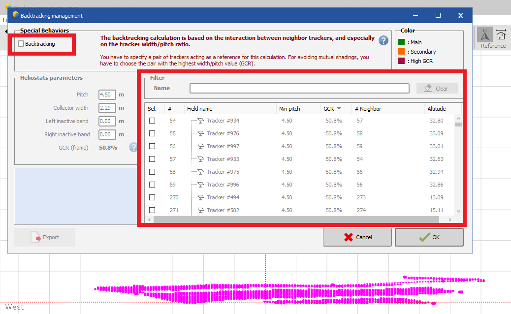
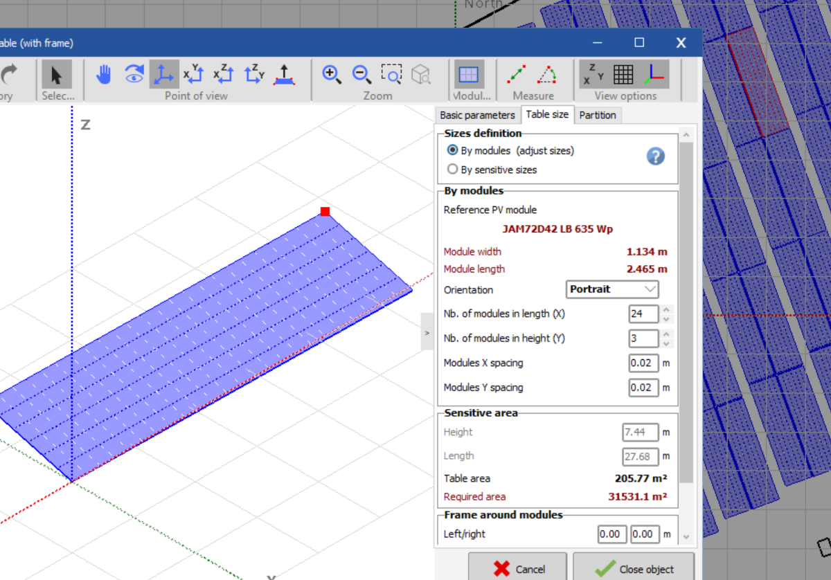
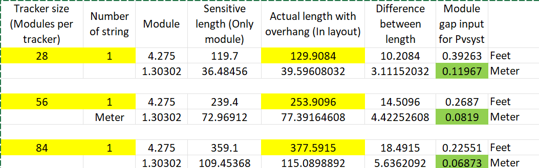
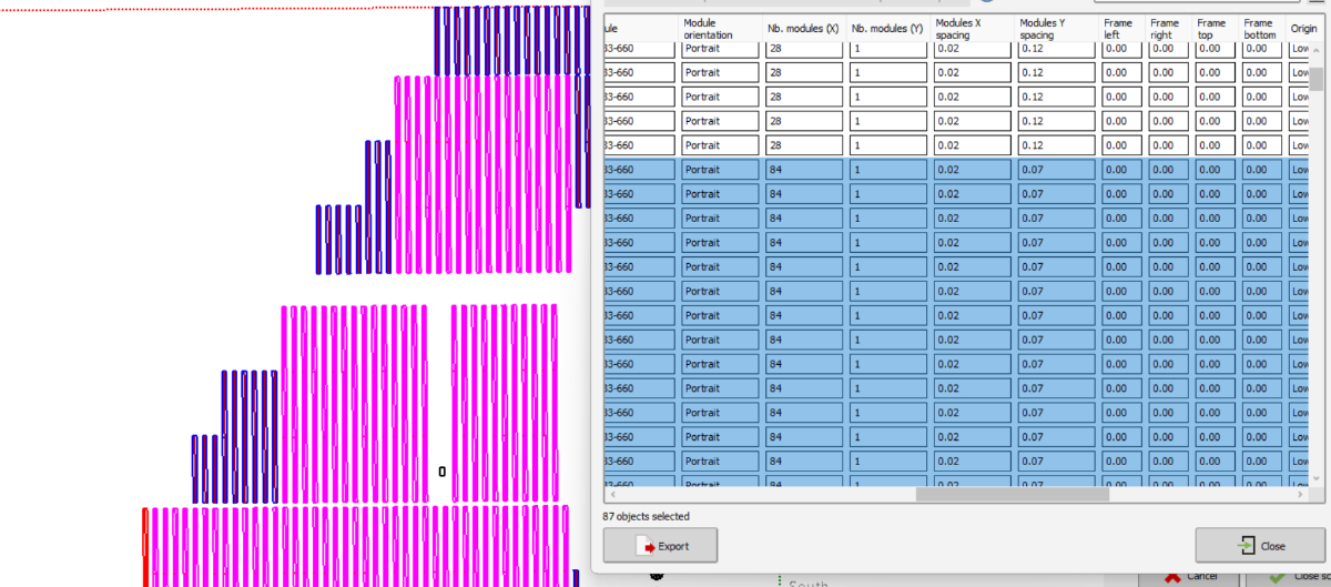
When PVcase exported PVC file imported into PVsyst, the tracker has more number of modules than it should be (87 modules per tracker instead of 84 modules ). I know this is due to the tracker motor gap and foundation gap for terrain following trackers (Multiple bays of 7 and 8 modules with foundation gap). I tried to divide all the gaps into module spacing to achieve the tracker length and changed the number of modules per tracker to actual numbers. See spreadsheet screen shot. In the process, I modified the rectangle’s length to equal the number of modules per string times the module width. However, this adjustment reverts to the original incorrect lengths when applied to trackers with different string configurations (2-string or single-string), showing 87 modules for a 3-string tracker instead of the correct 84. As a workaround, I’ve manually selected all similar trackers and altered the module numbers using the CTRL+G command. Question is- 1. Is this the correct method? If not, do we have other methods for simulations of terrain-following trackers with multiple bays? 2. Does this affect the thermal losses as modules have larger spacing compared to actual spacing (1 inch for reference)
-
I have created a CAD file and a .PVC file using PVcase, where my trackers and trees follow the terrain of a specific geography. However, when I try to import the .PVC file into PVsyst, I receive an error. In my assessment, it appears that the error may be attributed to the challenging terrain conditions. I will share the .PVC file if requires.
-
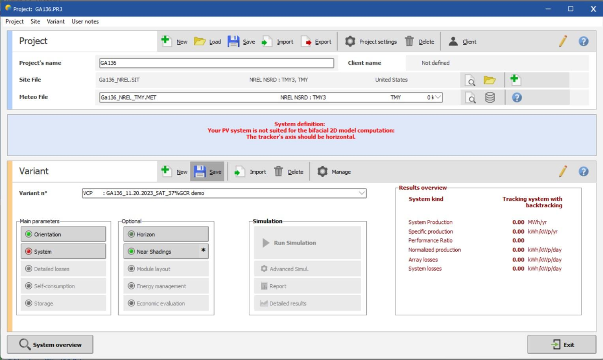
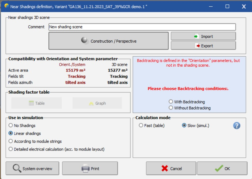
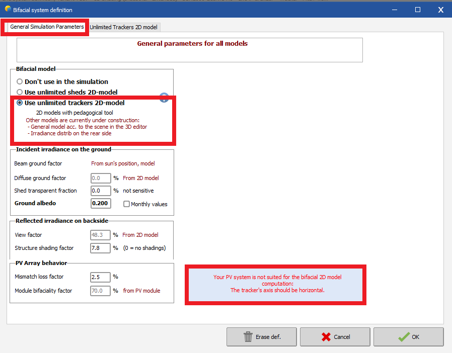
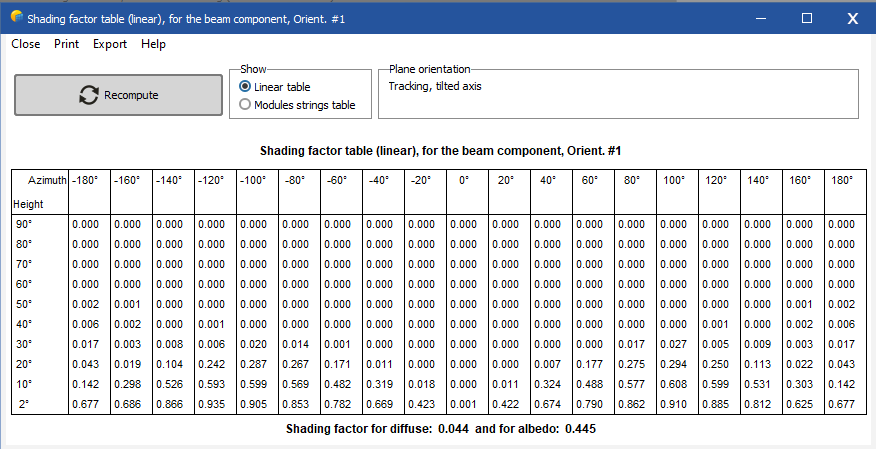
 I cannot simulate tracker's 3D scenes built with AutoCAD and plugings like PVCase or VirtuoSolar. With fix structure I was able to solve it by changing the tolerance in the "shading scene construction > tools > orientation management". Most of the scenes I am building are placed in sites where irregular terrain characteristics having NS tilted trackers with tilt angles from -8Dgr to 8Dgr is very common. In my projects computing 3Dscenes under this scenarios is a must specially because I need to use bifacial modules. PVSyst 7.2.12 Screen shoots How can I process this type of 3D scenes ? What I am doing wrong ? Thanks and regards M
-
Hi I am having issues with a project I m working on. I need to get P50, P75, P90, and P99 for a 320 MW design for a period of 15 years. I had read the help article about how PVsyst computes the distribution, yet I am not sure if it is safe to run the degrading tool at 3 years range and use the PR reduction as my correction factor or if running every year on its own is a must. The second option is the optimal solution but it takes a lot of computing power and time, which makes me consider this trade-off. Thanks for your help beforehand!


.png.9b71172eab032ab8b174a4248d03dc73.png)
.png.983c4f4b58fd4039480c92a6bf0e8da1.png)