
Michele Oliosi
-
Posts
811 -
Joined
-
Last visited
Everything posted by Michele Oliosi
-

Diferencia Producciones entre Informe y Excel Bachsimulation.
Michele Oliosi replied to AlvaroRuiz's topic in Simulations
Hello ! I'm leaving a translation in English - the forum communication language. ---- Good morning; After running several simulations of a certain project, I find that in several of the simulations, there is a difference in E_grid between the report and the Batch simulation. In the default simulation I have year 1, Pitch 6.5 meters, exactly the same parameters that I include in Excel BatchParams for the same conditions. I attach photos corresponding to the same simulation variable and without changing any data. I don't understand why this difference between report and Batch simulation, please if someone can help me I would appreciate it. Greetings to the entire community. -
Hi, here the main error is related to the bifacial modeling. Once the backtracking in the 3D scene and orientation agree, there should be no issue with backtracking. Please see the following help page https://www.pvsyst.com/help/bifacial-conditions.htm It should help you proceed with your simulation and see what is wrong.
-
3D SCENES- MULTIPLE ORIENTATIONS- BIFACIAL MODULES
Michele Oliosi replied to raulserr33's topic in Simulations
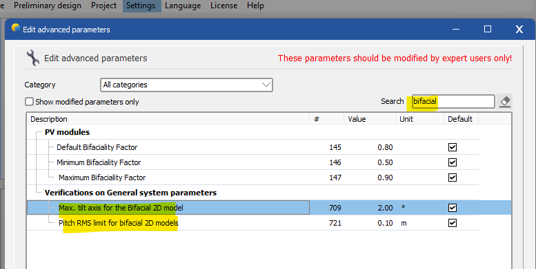
Home window > Settings > Edit advanced parameters.
-
You should actually change the following other parameter : "Max. tilt axis for the bifacial 2D model" This seems to be the reason for your problem, rather than the pitch
-
Horizontal and vertical PV modules as a system problem
Michele Oliosi replied to Filimena's topic in Shadings and tracking
Hi, At the moment, the bifacial model for the backside irradiance works only with a single orientation. You will have to split your system into two variants. -
Yes, PVsyst does at the moment recalculate the GTI from a GHI and DHI values. GHI and DHI may be generated from an input measured GTI. This is because as things stand, a MET file can be used with any orientation, i.e., it should be useable with an orientation other than that of the measured device. Moreover, the GTI itself does not have all the needed irradiance information, we need to decompose into diffuse components and direct component in order to make all calculations e.g., IAM or shadings. However, recomputed GTI and original GTI will in general differ by at most 1%.
-
How to calculate the irradiance on ground?
Michele Oliosi replied to squeezer's topic in Simulations
Hi, as far as PVsyst goes, this is not yet possible. The only variable that can be exported currently is the GlobGnd which gives you the average irradiance on ground in the system area (i.e. removing shading from the PV tables). But there is no spatial distribution. However we will indeed implement features that can help with agrivoltaic plants in the future. These features may come as soon as next year, although the schedule has not been set yet. -
V7.3.1 diffuse shade on trackers - issue with tracker selection
Michele Oliosi replied to Debbie's topic in Problems / Bugs
Actually the "automatic" selection is the historical way that was used in previous versions. We added the window for people to be able to have more control on the choice of trackers, while being able to use the "old" way. It became clear we had to propose other ways when we noticed the issue you point out. The related help page https://www.pvsyst.com/help/tracking_diffuse.htm -
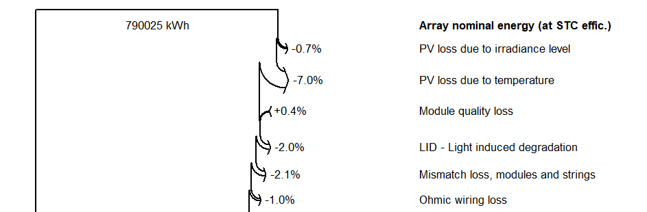
Dear Brij, It is incorrect to refer as the LID loss with respect to the nominal energy value. You have to consider the loss diagram flow: The LID is only accounted after the irradiance level, temperature, module quality losses (and other losses that may appear in your project). I.e. you need to change the value you use in B in your equation to account for these.
-
It is possible but it will only work if you use "arrays of tables", in particular if you have arrays that share the same pitch, orientation, and table sizes.
-
Correct partition layout for tables
Michele Oliosi replied to dennis.stu's topic in Shadings and tracking
Yes this looks ok ! -
@NIken if you can, in "Orientation" define two orientations each with their azimuth (e.g. -90° and +90°). Mixed orientation is the correct setup in the "System" window
-
Hi, did you also check the same operation hour by hour ? Since you have the 8760 file is a good cross-check in principle. Let us know how it looks.
-
Dear Ashley, There may be a problem with one or several of these files. If, for example, one of the files triggers an error (missing or nonphysical data), it could invalidate the TMY process. Can you send us the files at support@pvsyst.com? We can take a look at them.
-
PR correction on tracking systems
Michele Oliosi replied to Esteban1990's topic in Shadings and tracking
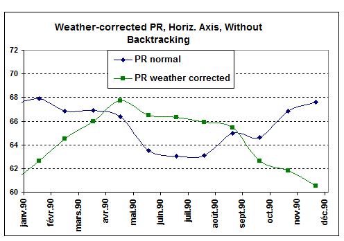
What is meant is the following: the tracking motion will exacerbate the seasonal variation of the PR, indeed in great part due to shadings. This is the corresponding graph in the documentation: In practice, this means that the goal of having a more stable PR throughout the year is missed. You can see in the graph that the usual PR is more stable. I am not sure what the results are with backtracking though, it may be worth checking.
-
Indeed, currently the custom import is limited to handling only a single year (i.e. you need to split your data into 10 files). The only way currently to import a series of years at once is if the data is in standard PVsyst format (https://www.pvsyst.com/help/meteo_pvsyst_standard_format.htm), so that it can be imported via the "Known format" import tools.
-
Yes of course, if you are estimating the production for several years, you should implement a degradation rate. 0.4%/year is the standard value in PVsyst and shown to be a typical value by various studies.
-
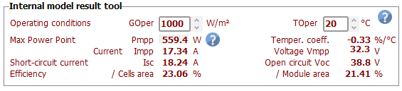
Other than the solution of changing the inverter limits and the minimum temperature, there is no other way. Your client should explain the calculation for Voc at 20°C that explains such an aggressive string sizing. In PVsyst you can check the module Voc at different conditions in the module window:
-
You can change the "lower temperature for absolute voltage limit". This should be the minimum temperature recorded over multiple years.
-
It is not possible currently sorry. Note that a second decimal place means between 0.01% and 0.1% depending on the GCR. This is well below the usual precision of the simulation; moreover, isn't this well below the typical significance of geometric measurements?
-
The approximation will probably be slightly optimistic for the bifacial gain. There is a way to not change your 3D scene tilts, it would be to go to the 3D scene > Tools > Orientation management, increase the tolerance (more than 20°) and click on Identify. In this way you can trick PVsyst into considering only the single average orientation with tilt 0°. The transposition gains for the front side will however be a bit off.
-
As mentioned, the warranty information (that you can enter on the bottom right of the window) will not affect the simulation, it is just indicative ! The orange curve (sum of average degradation factor and mismatch increase due to degradation) should generally stay above the black curve (warranty), to be realistic. If you really want to study a degradation = to the warranty, I would suggest entering 0 to both RMS values, and 0.55%/year in the "Aver. degradation factor". But I don't know why you would like to do so.
-
In your situation, the issue comes from having multiple orientations. PVsyst has currently some trouble handling imbalances between MPPT powers when they are both due to a difference in nominal DC power, or differences due to the orientation which causes the power to shift from a string to the other. The most critical is the case of configuration 1. I would suggest not to use the multi-MPPT for these 2 inverters of configuration 1. You should instead define a single orientation with 2 inverters while disabling the “multi-MPPT feature”. You can then define the orientation as “mixed orientation”. There is a cost, however, in that you should define your strings as either all with optimizers or without optimizers (I assume that is what OPT means). This approximation is necessary to be able to have a single sub-array and use the mixed orientation feature. I think you will end up with less clipping losses. But since this case is quite complicated, please let us know the results, and we will help you with it if there are still some problems. We can also move the discussion to emails, at support@pvsyst.com, as you prefer.
-
No, sorry, the results are not really useable like this. The backside irradiation model (bifacial model in PVsyst) is a 2D approximation that currently only works on single orientation rows. It does not take into account shading objects from the shading scene, as the roof you are adding instead of the other rows. What is the height of the modules ? Are they at ground level ? If so, you can expect zero bifacial gain. If they are on a structure that lifts the rows above ground (like on a carport) then there may be some bifacial gain. If the rows are well above ground, you can consider approximating your system by a tilt 0 flat disposition. In terms of bifacial gain, you should get an ok result.
-
Outlier treatment using non-linear regression
Michele Oliosi replied to Rafael Vilela's topic in Simulations
I don't know the reason for the -28W/m^2 specifically, but I imagine it is related to accommodating some measurements we used for the validation of the code. Physically, considering the balance of radiation at night (a clear sky has a low temperature) it is common that pyranometers give negative readings at night. For PVsyst it doesn't matter too much, since there are other “nighttime” filters that set the production to zero. Your research is definitely interesting, we'll gladly give it a read once published / made public. I am sure it may be appealing to other forum users as well.