
Stéphane Metz
-
Posts
112 -
Joined
-
Last visited
Everything posted by Stéphane Metz
-

More than 8 orientation, and cause error after imported 3d scene into pvsyst
Stéphane Metz replied to garf's topic in How-to
For this kind of problem, I recommend that you contact our support service directly at support@pvsyst.com. Please attach the relevant files to your email so that we can test them on our side. -
Unlimited sheds in PVsyst for PV power plant
Stéphane Metz replied to Mohamed's topic in Shadings and tracking
That's correct -
Unlimited sheds in PVsyst for PV power plant
Stéphane Metz replied to Mohamed's topic in Shadings and tracking
Hi Mohamed, You can optionally model the site in the PVsyst 3D scene by importing your satellite image in the background (pay attention to the scale), and using the zone editing tool. But I think it would be necessary at least to know the model of used PV modules. -
More than 8 orientation, and cause error after imported 3d scene into pvsyst
Stéphane Metz replied to garf's topic in How-to
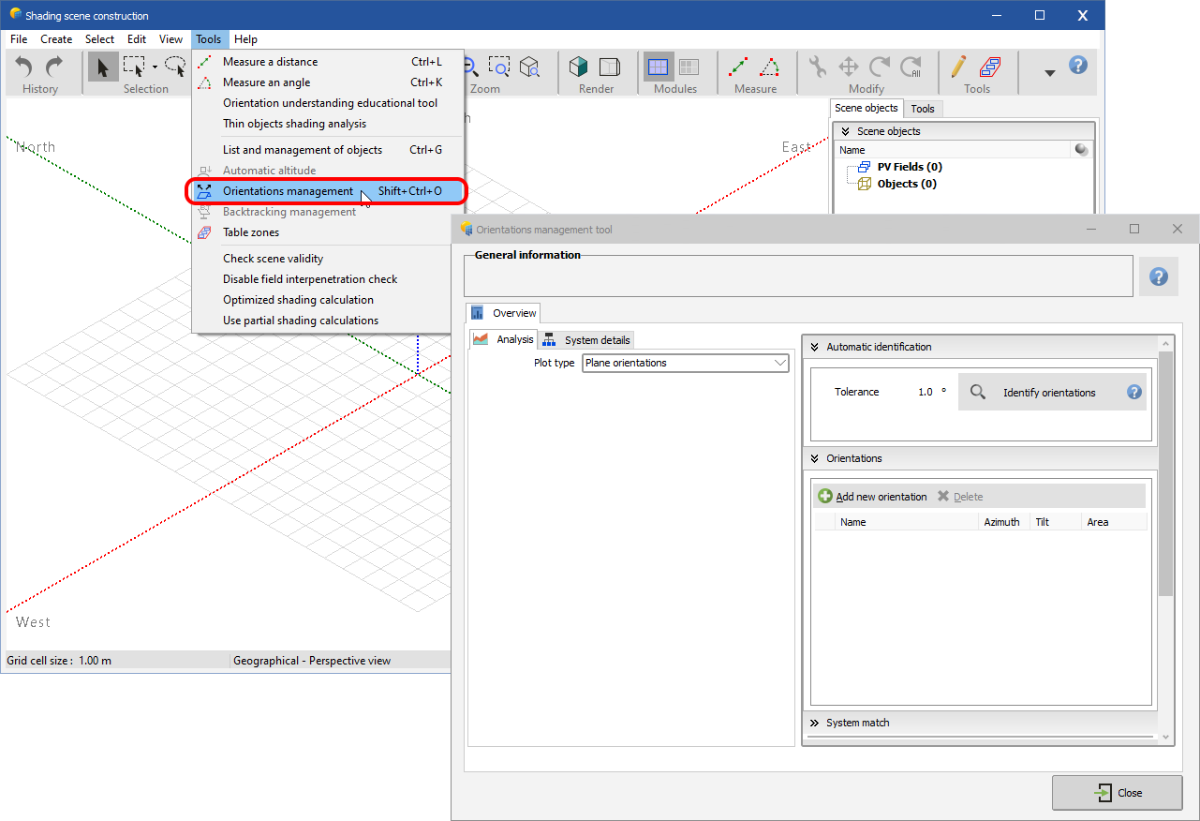
Hi Garf, You're right, currently PVsyst cannot handle more than 8 orientations. You will need to group some orientations together (averaged orientations) so that you get 8 orientations max. To do this, you can use the tool for managing orientations in the 3D scene: FYI, we are currently working on a new major version of PVsyst which will allow you to have as much orientation as you want. This version is planned for this year if all goes well.
-
How to modify a traker field into a dome/gable field ?
Stéphane Metz replied to Raffaele's topic in How-to
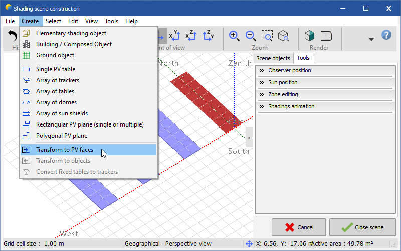
Hi Raffaele, Unfortunately this is not possible. There is a way to change followers to single PV tables, but not in dome structures: Transform tracker to object: Then transform object to PV faces: I don't know if this will help you ?♂️
-
Hello tlry75, Currently, it is not possible to copy/pasting zones directly. But you can right click on the zone in the tree view, and click on "Select all objects in group". You can then copy/paste selected PV fields on other similar rooftops:
-
Hi Wailsalaoui, Instead of drawing a polygonal zone, draw a rectangular zone and remove the extra PV fields afterwards, like this: Regards,
-
IAM losses higher with newer modules?
Stéphane Metz replied to S Groenveld's topic in Shadings and tracking
Some answers are given here: https://forum.pvsyst.com/topic/2667-sandia-model-database-no-longer-supported -
Hi Iulian, Thank you for these suggestions, I'll be sure to pass them on to the dev team. Just a note regarding the accuracy of the shading scene, it is not necessary to have precision to the nearest millimeter, as this will have very little impact on the shading loss factors. Loss differences of 1/1000 knowing the variability linked to the weather do not really make sense.
-
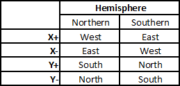
Hi AJ, As you mentioned, the ground CSV files are XYZ coordinates. PVsyst axes depends on the location of your site (northern or southern hemisphere): You can find more details about the PVsyst reference system in our help: https://www.pvsyst.com/help/index.html?global_referential.htm. You can easily rotate your ground by 180 ° after importing with the rotation tool: . Just select your ground in the right tree view, and rotate it. You can also have fun modifying your XYZ coordinates from Excel.
-
"Maximum Field/Shadings Area ratio" ignored
Stéphane Metz replied to johank's topic in Problems / Bugs
Pay attention, the values you show by screenshot are far from the default values: The "Maximum Field/Shadings area ratio" parameter in the project parameters corresponds well to the "Shadings: absolute maximum shading/field area ratio" from the advanced settings. The label is wrong, you have to read "Shadings/Field" instead of "Field/Shadings". I will correct the text in the software.
-
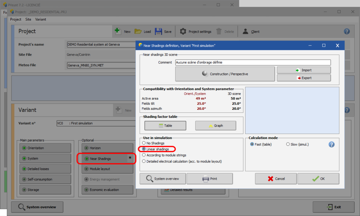
Hi bendesa1962, Check that the shading calculation is selected in the near shadings dialog: Also, check in the report options that you are generating the near shadings page: Regards,
-
merge surface csv with export pvcase
Stéphane Metz replied to Manfredi990's topic in Shadings and tracking
Hi Manfredi, PVsyst always brings imports closer to the origin in order to avoid having too large {X, Y, Z} values (thus avoiding rounding problems). With the PVC file, you can disable this option at import time and change the translation offset to your liking: However, for CSV file this is not possible. But you can easily calculate the offset by looking for the {X, Y, Z} values closest to the origin from Excel. After that just move the ground object in PVsyst (or include this offset in the PVC translation offset during import). Also, it is possible that there is a rotation of 180° on the azimuth depending on the chosen hemisphere. More detail about PVsyst coordinate system here: https://www.pvsyst.com/help/index.html?global_referential.htm
-
"Maximum Field/Shadings Area ratio" ignored
Stéphane Metz replied to johank's topic in Problems / Bugs
Area ratio = Shading area / System area -
PVsyst staff dedicated to answer question in the forum
Stéphane Metz replied to Barbadori's topic in Suggestions
We are also looking to change the forum engine in order to offer a less old and osteric forum 8-) -
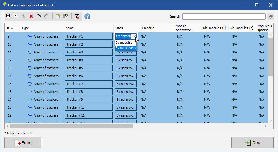
Hi Andreos, Grouped modification also works with trackers in the same way that single tables (select all then click on one 'By sensitive' cell, be sure that you keep all selected): If the initial size of your trackers does not match the defined module type and number, it is completely normal for the size of your trackers to change. In the same way, you can modify the 'PV module', 'Module orientation', 'Nb. modules' in X and Y and 'Modules X and Y spacing' parameters: You can go back in case of error by doing undo/redo (CTRL+Z/CTRL+Y). You can help yourself with the tutorial available on our Youtube channel:
-
"Maximum Field/Shadings Area ratio" ignored
Stéphane Metz replied to johank's topic in Problems / Bugs
Hi johank, A large discrepancy between your system definition and your 3D scene undoubtedly means there is a sizing error. Please check your system definition and your 3D scene. The smaller the gap between the two, the more consistent your definition is. -
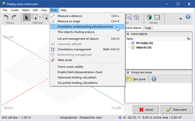
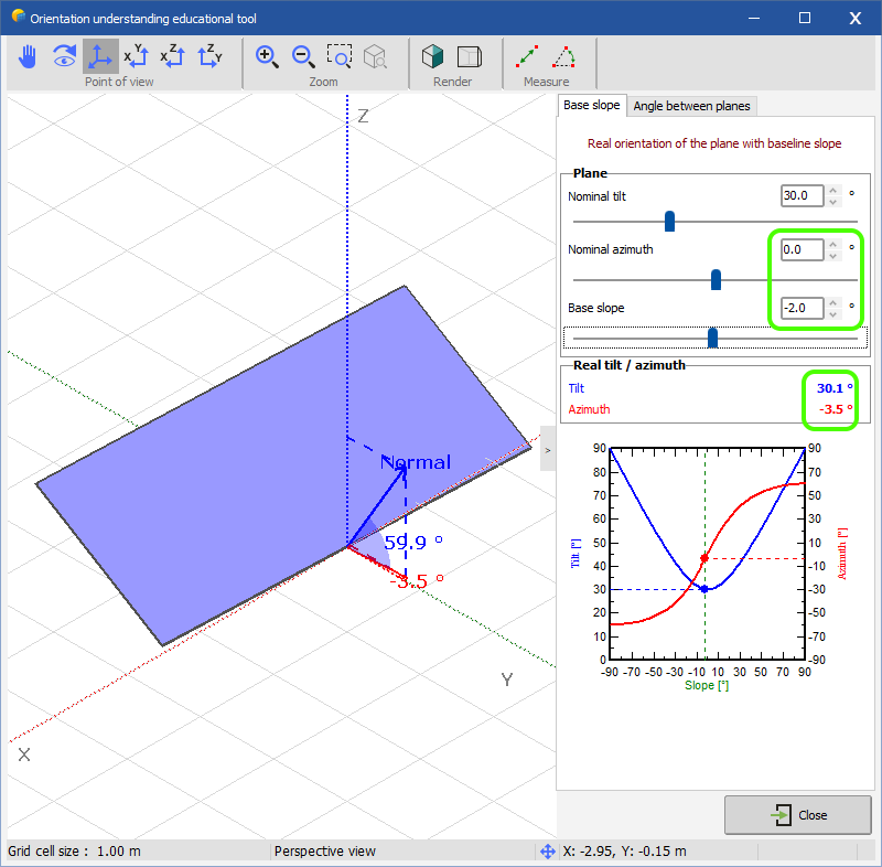
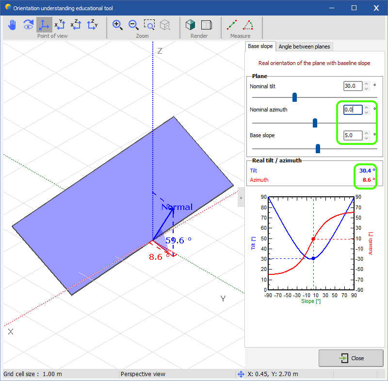
Hi Gmiret, Several thinks to say: Be careful with the use of H2P files coming from Skelion. Indeed, the H2P file format was defined by PVsyst jointly with the company Helios3D. Skelion adopted this file format without strictly adhering to the format requirements (they never asked us for the format specs). It is therefore possible that there are import errors with this kind of files. As you are using Sketchup it is best to use DAE or 3DS formats. If the slope angles are different, the resulting tilt and azimuth angles will also be different, you'll find an educational tool in PVsyst to better understand this concept: With slope = -2°: With slope = 5°: It is quite possible to have trackers with different tilts in the same orientation. It is important to understand that if the tilts of your trackers are not the same (often the case of trackers on uneven ground), the tilt of the orientation will be averaged. In order to avoid calculation errors, PVsyst limits the difference in tilt between the trackers to 4°. If the tilt difference exceeds 4°, you'll have an error. To fix this error, you can: Either adapt your shading scene to limit tilt differences; Or modify the limit value (4 °) in the advanced parameters of PVsyst (be careful to keep a reasonable limit value, because the calculation could be wrong if there is a too great disparity between your tilt angles): Backtracking should work, but be careful with the use of backtracking on a hill, it's not necessarily more efficient that without backtracking. More details in our documentation: https://www.pvsyst.com/help/index.html?backtracking_onhill.htm If you still cannot fix your project, do not hesitate to contact us by email at support@pvsyst.com.
-
Hi lenergy, The current version of PVsyst is now 7.2.11. I believe this problem has since been fixed.
-
Hi dtarin, I raised the topic to the DEV team, thanks for the suggestion ?
-
Hi dtarin, The current verification system in PVsyst stops at the first discovery in order not to slow down further processing. However, I understand the usefulness of having all the errors at the same time. I will discuss this internally, perhaps this feature could be added in our roadmap ? ?♂️
-
The current limit for the number of sheds is 999. This limit is intentional and seems sufficient to us. But it is quite possible to create several array of sheds each containing 999 sheds, which allows to have a larger number.
-
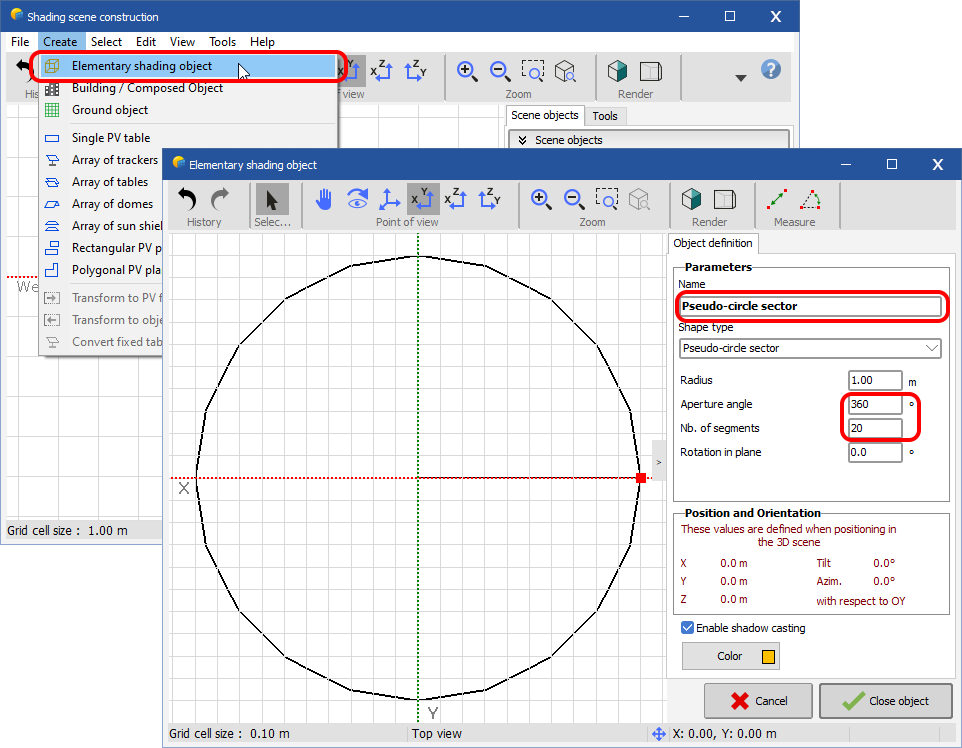
Hi roberto.bissanti, It is not yet possible to make a circular area, on the other hand, it is possible to make a polygonal zone approaching it: 1. Create a circle (elementary shading object) as a sketch 2. Then draw a zone over the sketch
-
PVC import failure with 7.2.7
Stéphane Metz replied to gonecrawfishin's topic in Shadings and tracking
Hi gonecrawfishin, The "Orientation management" tool is not available for trackers. Do your PVC files contain trackers or fixed planes? -
Power Units Do Not Save in Output File Definition Window
Stéphane Metz replied to kjs55's topic in Problems / Bugs
Hi ksj55, I just tested this in v7.2.11, and you're right, units are not loaded. I will report the bug to the dev team. Thank for your feedback