
Michele Oliosi
-
Posts
815 -
Joined
-
Last visited
Everything posted by Michele Oliosi
-

Bifacial and Monofacial Panels in a same system
Michele Oliosi replied to Omama Zaheen's topic in Simulations
Sorry, at the moment it is not possible to have both monofacial and bifacial modules in the same system in PVsyst. This will be addressed in the future. -
Hi ! https://forum.pvsyst.com/topic/3085-electrical-shading-losses-in-versions-73x/
-
energy loss diagram trouble still pending since 7.3.1 !!!
Michele Oliosi replied to HLubke's topic in Problems / Bugs
After trying with the aging I was able to reproduce the error, although not in an extreme fashion as what happens in your project. Nonetheless, I will be able to post a detailed ticket to tackle the issue. EDIT: the error also appears in standard simulations in some cases. -
energy loss diagram trouble still pending since 7.3.1 !!!
Michele Oliosi replied to HLubke's topic in Problems / Bugs
Hi, I am sorry you are having such a bad experience. We will of course look into it. Regarding the quoted post, we had been waiting for a project that shows this error. You now mention the error is related to using the aging tool. Can you confirm that we are talking about the same error described here, with the updated info that you are using the aging tool ? -
Cutting it short: the P75 yield is added to the report of a single TMY or reference year simulation if you go to Energy management > P50/P90 estimation. PVsyst cannot provide automatically a 25 year list of P75 values at the moment.
-
Hi, I don't think that the concepts of P50 and P75 always apply well to simulations over multiple years. Basically you get a P50 result when you simulate with an "average year" and "average parameters". When you run 25 years of simulations there are two cases: - You are using the same weather input file (an "average" one) for all of the simulations, and what changes is just the aging. In this case, it could make sense to call the results for each year a P50 estimate. However the P75, P90 etc depend on the uncertainty of the parameters (which you can define once in Energy management > P50/P90 estimation). For 25 years you would probably need to increase the uncertainty of the aging parameters as the years go by. This is not yet implemented. - You are using a time series to run 25 years. In this case you are not using "average weather files". So it is not possible to get a P50 value from that. You can use a 25 year time series to get a TMY with PVsyst. Using that file as "average weather" file will bring you back to the previous point. The multiplier to get the P75 value depends on the width of the distribution. Given a standard deviation sigma, the multiplier is (1-0.674*sigma).
-
Dear Yann, Could you reproduce the comparison with 7.2.21 instead of 7.2.6 ? There have been many patches in between, and several major errors have been corrected. I would feel more comfortable comparing more stable versions. There have been some changes in the electrical shadings evaluation. For this I would advise reading: The horizon losses have also had an improvement. From the release notes in 7.3.3: - Horizon (far shadings): the calculation of the horizon shading has been corrected for times the sun passes the horizon line. This may slightly change the simulation results
-
byfacial system definition for fixed panels
Michele Oliosi replied to C. Amorevole's topic in PV Components
In fact it is compatible, as long as there is only one nominal orientation, that all tables have the same width, and that the pitch between tables is fairly regular. You can check this help page for more details: https://www.pvsyst.com/help/bifacial-conditions.htm -
Uc > 32 seems to be very optimistic, although I do not have a strong basis for this argument. Since Uv = 0, this value depends on the particulars of the site (average wind speed) and of course the structure so it is difficult to say for sure. We do not know of any studies that recommend this value, but we may not be up to date. I would encourage you to discuss with your client the fact that this is well above the usual PVsyst defaults.
-
Yes that is correct. For example if your inverter tends to heat up, you can set a few degrees to indicate that it is warmer than the ambient temperature.
-
The wind velocity should be defined in the MET file, and will usually change hour by hour. If you want to input a single "default" wind velocity you can simply set Uv = 0 and Uc = 25 + 1.2*3.4. This will be completely equivalent as having Uc = 25 and Uv = 1.2 with constant wind velocity 3.4 m/s.
-
The option "external ambient temperature with shift", allows to define that the inverter temperature will follow the ambient temperature, plus or minus a constant value in degrees that is defined as the "Temperature increase". For example if you define a temperature increase of 5°C, and at a given time the ambient temperature is 38°C, then at that time in the simulation the inverter temperature will be 43°C.
-
@herminator are you sure that it is only in the report? As mentioned these values should come from the 3D scene > Tools > Backtracking management, and these are important for the simulation. I woudl suggest double checking that.
-
Bifacial Module Simulation with different tilts & azimuth
Michele Oliosi replied to sajid s46's topic in Problems / Bugs
To be precise, you could choose either "unlimited sheds" or "fixed tilted plane". However since in your case you would have 3 orientations, you would have to use "several orientations" and that is not compatible with the bifacial model. At the moment therefore, the only way is to make two different variant simulations, one for the bifacial part, another for the rooftop two orientations -
It may be related to a new bug that affects PVsyst when importing 3D scenes: the backtracking parameters are not always updated. Until we have corrected the bug, you can go to the 3D scene and open Tools > Backtracking management. There you can select a tracker in the list or enter the values manually.
-
Electrical shading losses in versions 7.3.X
Michele Oliosi replied to Michele Oliosi's topic in Shadings and tracking
The behaviour above will be retained for all 7.3 patches, including the latest one 7.3.4. As mentioned we are working on an overhaul but it will be made avaiable in a new sub-version: PVsyst 7.4. -
Array Partitioning with Sheds Fields
Michele Oliosi replied to Rachel Hamilton's topic in Shadings and tracking
We have an article on this topic if you want to go further ! https://www.pvsyst.com/wp-content/uploads/2022/11/Article-PVSEC-2021.pdf -
Array Partitioning with Sheds Fields
Michele Oliosi replied to Rachel Hamilton's topic in Shadings and tracking
Hi ! In fact the interpretation of partitions (or as they are called in this window "rectangle-strings" which I think we will change eventually since it is confusing) is a bit more complicated than a string. It's worth going back to the factual definition. These partitions represent a group of PV modules (or submodules even), whose power is lost, effectively, when part of it becomes shaded. The concept of partition mostly makes sense when the shadings are regular, i.e. they tend to cover all modules within the same group in the same way" Typically this is the case with mutual shadings, or shadings from "wide" shading objects (e.g. a row of trees, a fence, a wide parallelepiped). This is because when the shade falls on the PV tables in a regular way, then one can by simple considerations find out whether the power is lost or not. Take for instance a string of modules in portrait: if all the bottom cells are shaded, then all submodules are limited in current because of the shaded cells. By extension, the whole string can only support as much current as the shaded cells allow. In this case part of the partition is shaded, then the whole string becomes inactive. Now, even if you split the above string of modules in portrait into three tables (like in your example but with modules in portrait), as long as the shades that cover the tables are similar (usually because they form regular rows) the situation is the same: when all the bottom cells are shaded, then you will lose the power from the three tables. For this reason, in the case of regular rows, no matter whether the string is split among tables, you can still safely define one partition in the length of the table, as though your strings were shorter. In the partition framework, there is usually no need to define fractions of partitions. There can be more complications when using the partition framework to define electrical shadings. In some situations, for example for half-cut modules in portrait, or for any modules in landscape on one module-wide tables (such as your example), one should not define a single partition per string, but rather two. This is because a shadow on the bottom cells does not invalidate the power of the whole string. Due to the bypass diodes and cell layout, about half the power is retained. TLDR: in your case, I would put two partitions in the height of the table for all of your tables. The reasons for this are: when the modules are positioned in rows, the shadings are usually the same for all the modules. You therefore don't need to define fraction of partitions if your strings are split across tables. your modules are in landscape so you can define two partitions in the height (axis Y in your screenshot) of the table. Btw this is usually beneficial to the yield. -
Hi, You can check your inverter night consumption (System > View inverter details), transformer night losses (Detailed losses > Ohmic losses), or auxiliaries (Detailed losses > Auxiliaries). All these may consume some power at night. Since there is no solar energy production, this can lead to a negative value of E_Grid
-
Simulations are extremely slow after 7.3.4 update
Michele Oliosi replied to Murat Karakum's topic in Simulations
Hi, if reverting back to a previous version did not change the simulation speed, it probably is related to some parameters in your project. We'll gladly have a look at what is causing the slowness. You can send us your project for review at support@pvsyst.com. -
Very good question. Indeed in PVsyst the view factor calculation incorporates the IAM factor, according to the Fresnel smooth glass model.
-
Hi indeed, I think you don't need to add up voltages, the strings are basically in parallel.
-
Change in far shading losses going to version 7.3
Michele Oliosi replied to laurahin's topic in Problems / Bugs
The horizon model has been improved in 7.3.3 and it should also cover the bug we mentioned. The results may still differ a little from 7.2.21 but this is due to the improvement: we now consider more correctly, within each hour, the fraction of the sun trajectory that is behind the horizon. Please let us know if you experience anything strange agin. -
Thank you for your comments! Okay, thanks for the remark. We will then have to review again the different data sources and see what usable data we find. We'll see to keep up to date on this. Indeed physically it is not so complex (although one needs to be careful with a few models, for example the thermal one as you mention). But purely in terms of code we would have to change a lot of things. As mentioned, we are actively working on the subject of subhourly clipping, since there are still few questions to be elucidated. We will present further conlcusions of our studies at PVPMC2023, and the poster should be made available online. With these studies we are gaining a lot of new understanding that should also help in the longer term to transition to sub-hourly simulations, if necessary.
-
shade scenary: tracker are not compatible
Michele Oliosi replied to C. Amorevole's topic in Shadings and tracking
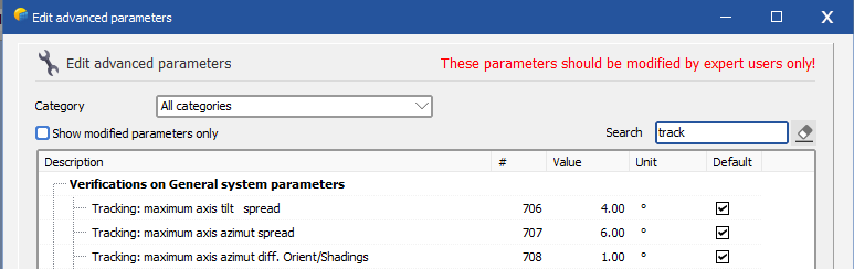
Hi, The Orientations management works in the fixed tilt tables case, but not for trackers. At the moment in PVsyst, you can have only a single tracker orientation. If you want to proceed by considering the average tracker angles nonetheless, you can change the following advanced parameters (home window > Settings > Edit advanced parameters): This should help you bypass the error.