Georgy PM
-
Posts
3 -
Joined
-
Last visited
-
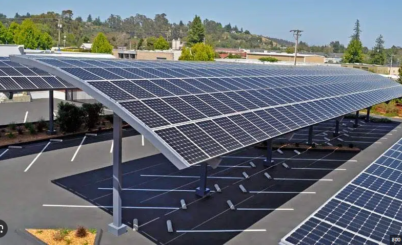
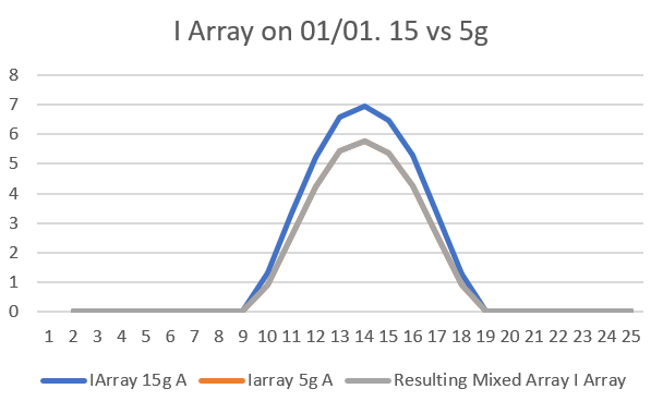
Dear Muhammed, Thank you for your previous response, I tried to convince everyone of avoiding mixing orientations, but more interesting cases are appearing. For instance, some clients are requiring more “stylish” solar carports, things like this: Hence, it is harder to match module’s orientations and strings (like if solar installer’s life wasn’t already hard enough 🙄). Since in cases like this one we have to absolutely mix two different orientations, the big question that arises now is : how much appart the orientaiton can be ? Lacking availibility to think about complex formulas of irradiation and photo current, I tried to get the mismatching losses directly from PVSYST results. First, I made a simple simulation with 4 panels with 15degrees of inclination, then other 2 four modules systems with 5 and 10 degrees (same azimuths). Then, I exported the hourly results and “mixed” the Array’s outputs (for a maximum of 8 modules, only 2 orientations at time), follwing two simple rules: voltage of each group of 4 modules are added, and the current of the string is the smallest produced by any of the 2 groups of 4 modules. For instance, the results of the Array current for each group and the mixed results are shown below (Iarray5g and the mixed are the same): Finally, in order to estimate the loss produced by the mismatching, I did: I mean, the loss would be the ratio between the he total energy that one would get by having each group connected to independents MPPT divided by the mixed E_Array. Since the almost linearity of the inverter’s output, the E_Grid should have a similar reduction. By mixing 5 and 10° orientations I got -1,98%, 10 and 15° -1,64% and 5-15° -3,54%. They seem big to me as expected, so I will try smaller orientation variations in order to get less than -1 or -0,5% of losses. Economically this would be acceptable since it is much more expensive not doing the installation 😊. Before continuing, I wanted to have your opinion about this approach. Do you think that we can reproduce this procedure for calculating the mismatch losses for much more complex systems? For instance, having 1 module with one orientation and 7 with another, or varying the Azimuths (which will start to shift the output’s curves). Below I send you two links where you can download the project and the excel file. Many thanks in advance for your feedback. 원주공항 Project v2.zip 원주공항 Project_VC5 Az0, 15 vs 10 g, 4PV.xlsx Best regards

-
Dear PVSYST team. First of all, my thanks for the latest software updates, the improvements are very welcome. Now based in South Korea, I have very particular cases of systems with modules in series having different orientations and/or inclinations. I insisted a lot to my colleagues that this would result in very high mismatch losses, due to the difference in current produced by each module. However, I was asked a very good question (which I think is perfectly valid): how far apart in orientation can you connect modules in series without incurring significant losses (less than 1%, for example)? Would it be 1 degree apart? or 2? Is PVSYST able to simulate a string of modules with 2 different orientations? I've been trying to do it for a while, unfortunately without success, so I'd be very grateful for your help. Thank you very much in advance. Bon début d'aneee !
-
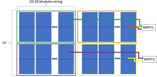
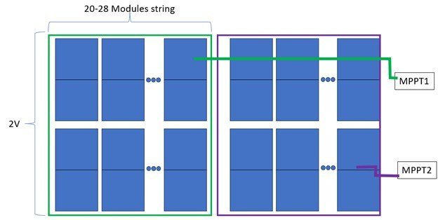
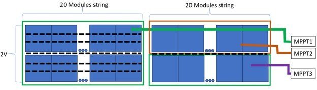
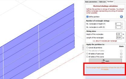
Hello PVSYST team, I have a couple of question regarding the partitioning according to your guide (for the new version 7.4, June 2023). In the summary for common cases, you indicate how to make the partition in the shading scene when one has 2 or more rows of modules in parallel. I want to confirm with you, how many partitions should I apply when the strings are not in parallel vertically, but horizontally and connected to independent MPPT of a string inverter (1500Vdc system)? Here some of my cases: 1. Half cut module in portrait, 20 to 28 modules horizontally in series, 2 or 3 rows per rack. Each row is connected to an independent MPPT of the string inverter. According to the guide, I understand that I should apply 4 partitions (if 2V, 6 partitions if 3V), is it correct? 2. Same configuration before, but with modules in landscape instead. Following the guide, I should apply 2 partitions (if 2V, 3 partitions if 3V). Is it ok? 3. For the same configurations, but with Bifacial First Solar modules instead (6 modules in series, horizontally cabled). How should it be done the partitioning? 4. When having the modules cabled in U and 2 string in parallel (Half Cut, portrait), I understand that I should apply 2 partitions (if 2V, 3 partitions if 3V). This also applies when assigning the strings to independents MPPT? 5. When having half cut modules in landscape, 3x partitions (6 in this case) should be applied for modules connected in U. When they are cabled horizontally, x partitions should be applied (2 in this case). This also applies when assigning the strings to independents MPPT? When having racks with both U and horizontals strings assigned to the same inverter, I get the partition shown below. However, this seems to me that I should expect less shading losses when cabling in U, than when cabling horizontally. But electrically does not seem logical to me because when the bottom modules are shaded in the U case, the current of all the string is affected. I the second case, only the shaded row is affected. Hence, I would expect more shading losses when cabling in U. In addition, note that when partitioning a module in 2 or more, the following warning message is shown below. The message should be ignored in that case? 6. When 2 or more rows of strings are cabled in parallel (6 modules in series), what should be the partitioning for the Bifacial First Solar modules? Guide link : https://www.pvsyst.com/help/shadings_partitioninstrings.htm Many thanks in advance for your help, Best regards, Georgy