André Mermoud
-
Posts
2075 -
Joined
-
Last visited
Everything posted by André Mermoud
-

Battery discharge power outside the operational time
André Mermoud replied to Solaranger's topic in Problems / Bugs
I don't know. Please send us your whole project, using "Files => Export project" in the main menu. e-mail: support@pvsyst.com. -
Sorry, with the bi-facial model presently implemented in PVsyst, you cannot define a bifacial system with several orientations. This will be possible in the next version 8.0.0.
-
The grid limitation principles are fully explained in the help " Project design > Grid-connected system definition > Grid power limitation" Now I don't have any knowing of the fact that E_Grid exceeds the grid limitation. Please send an example-project. In the previous post, it was not the E_Grid, but the EOutInv value which exceeds the grid limitation.
-
Yes, this is possible as an approximation, when your system is not too uneven. NB: if you have warnings (for example axis tilt differences too high) you may modify the limits in the advanced parameters.
-
Solar radiation below the semi-transparent PV panels
André Mermoud replied to Giovani Dávi's topic in Simulations
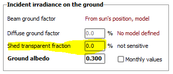
When you want to evaluated the irradiance on the ground, you will use the Biacial option. In the bifacial system definition, you have this parameter: The ground irradiance calculation will take this parameter into account.
-
Yes, as soon as you put a component in your workspace, it will appear in the PVsyst lists. In the lists, the components defined externally appear with a grey background.
-
PVsyst cannot obviously reference all batteries present on the market. You should use a battery with similar characteristics as your battery model. I.e. similar in technology, voltage and capacity. You may also use a "universal" battery, for which you explicitly define the voltage and capacity. NB: the simulation result is not very sensitive to the exact capacity of your battery pack.
-
These values are a result of the sîmulation. Fixing their value doesn't make sense. When you need energy for feeding your needs during the night, you don't have any solar power at disposal. Your system has to draw this energy from the grid. During the day, your load may need more power than the available PV power at this time: again, the grid will provide the complement. The only way to avoid this would be to store energy in a battery.
-
Sorry, it is not possible to get such a plot directly from PVsyst. The only way is to create a CSV hourly file during the simulation, including the variable E_Load (or any other desired energy quantity). And then you have to elaborate your plot from these hourly values in EXCEL.
-
The OND files are meant for internal use within PVsyst. We don't ensure support about them. Exceptionnally, I can say that the Nominal AC power mode (active or apparent) is described by the bit #21 of the flags.
-
Yes, the DC converters diectly connected to the PV array are not yet implemented in PVsyst. Please have a look on the help " Project design > Grid-connected system definition > Grid systems with storage > Grid storage, system architecture "
-
The instantaneous powers are not appearing on the report. You can get the E_Grid values in case of overload by creating a CSV file of hourly data (button "Advanced parameters => Output file" and analyse the hourly data when the inverters operate in overload conditions.
-
This is obviously the main result of the PVsyst simulation. However you have to define the parameters of these losses in the "Detailed Losses" section. For the results, see the Loss diagram.
-
simulation of low irradiance conditions (how to adjust module panfile)
André Mermoud replied to Age's topic in Simulations
The Rserie adjustment is indeed the main parameter that manages the low-light behaviour. You can adjust it for getting the desired low-light performance, i.e. matching your experimental points if available. NB: If you are in the page "Additional data => Measured low-light data", this is a tool for importing the detailed measurements concerning your module. This tool is an independent help, the parameters you set here are not the parameters of the PAN file. The PAN file may have different STC values, and when you exit this tool PVsyst will ask if you want to keep the low-light performance of the model established here. If so, as the STC are different the paramerers RSerie and RShunt suited for the PAN file may be different as in this tool. -
This is not possible in PVsyst in the present time. This is indeed not pertinent in most cases: why charging the battery if power is available from the grid when necessary ? Now there may be particular cases where this cous be useful. For example: - in case of very weak grid, it could be useful for keeping a minimum of charge in the battery, for ensuring consumption in case of grid failure. - If you want to store energy during low tariff period, for restituting it during high tarif period. However this may be done in any system, even without a PV production. This is not considered in PVsyst.
-
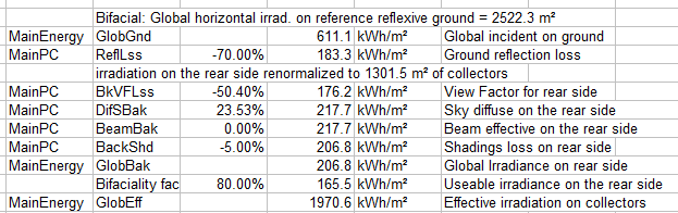
The calculation sequence is as shown on the loss diagram. For getting the values and acronyms in EXCEL, you can open the report, Menu "Export > Loss diagram values". You will get a table to be pasted in EXCEL: Here you can see the flow of the calculation of the energies. The GlobBak value is accounted after taking the rear shading losses into account. Now the problem of measuring this value on-site is really difficult. The irradiance received by the backside is highly dependent on the position in the table (top to bottom in sheds, or from axis to edge in a tracker). There is no real consensus about how to measure this value on-site. Please see the help "Project design > Results > Performance Ratio" for a more detailed discussion of this problem.
-
Yes, you can indeed define any kind of customized plot to be accumulated during the simulation. In the project's dialog, please open "Advanced simulation > Special graphs". Now for your case a much better way would be to create a CSV file of Hourly values, that you can manage in EXCEL. For this open "Advanced simulation > Output file". Here you can choose any variable among the 100+ variables of the simuation.
-
Gain in Battery Energy (instead of loss) while Discharging
André Mermoud replied to PVsystUser's topic in Simulations
I had asked the project because I had a doubt about the E_Grid and EOutInv values, on the 05/06/90 10:00 .. 14:00 records. Normally, PVsyst calculates the production during the best hour of the best clear day of the year (according to the clear sky model), for an advice about the sizing of the PNom you should define for your inverters. You have indeed specified your inverters pack using this value (374 MW), and this is “a priori” correct. With this definition, we expect that the real production exceeds the PNom value only very exceptionally. In your case, it exceeds it during 5 consecutive hours, which I found very suspect. This is the reason why I asked for checking the input meteo data – which seem indeed excellent. With your project I found the explanation: you have defined a bifacial system, so that the real power may exceed this PNom value. I had not anticipated this possibility when defining the “Max. output power (clear sky)” value. This should be done in a future version. -
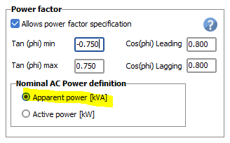
This is quite normal, and fully explained in the help “Project design > Grid-connected system definition > Power Factor”. Your inverter PNom is very probably specified in terms of Apparent power [kVA]. In the “output parameters” page you should have: Therefore if you are operating with CosPhi = 1, the PNom will be 2155 kW, but if you operate with a power factor of 0.95, the power limit will be Pnom = 2155 kVA, corresponding to an active power = 1048 kW. This doesn’t represent an explicit loss, therefore this doesn’t appear on the loss diagram. However you will se a difference in the overload losses.
-
I don't see well what you want to do. For such an approximation, you can use the Input/Output diagram as reference (draw E_Grid as a function of GlobInc). Without power overload, this should fit this distribution with a rather well defined straight line. You will have a dispersion of points, depending namely of the array temperature. You should apply the temperature model for the array temperature, based on the ambient temperature. If you apply the temperature loss to each hourly point, you should probably reduce the dispersion.
-
First question: this shading Module Layout calculations from the I/V curves is explicitly done at each step of the simulation. The effect of the partial shadings on the whole array is fully explained by the I/V curves. Second question: in this case the "Linear shading" (irradiance deficit) is 0.4%, and the electrical loss is null. The repartition between Linear and Electrical losses is not always quite reliable, as the linear shading loss is calculated globally for all tables of the concerned orientation, when this electrical calculation concerns one MPPT input. But the global loss is correctly calculated.
-
PVsyst doesn't treat the integrated storage systems (all-in one hybrid systems). It needs to specify the battery pack, the charging and discharging properties independently. As I understand, you have datasheets for 2 battery systems: the BF100 series (with 3 different capacities) and the Powerstone. The Powerstone is an assembly of 15 battery modules, but I really don't understand their definition: the voltage is specified as 512V for 100 Ah. This means an energy storage of 51.2 kWh. I suspect that there is an error on the datasheet, the voltage should be 51.2 V. I will include these batteries in the database for the next version of PVsyst.
-
The Module Layout calculation is based on the effect of shades on each submodule (i.e. set of cells protected by one by-pass diode). Therefore the submodules layout within the PVmodule should be well defined. The Module Layout calculation is only develoed for standard modules, with submodules "In length", or twin half-cut cells. See the help "Physical models used > PV Module - Standard one-diode-model > PVModule Structure > SubModules layout". The Voltec modules have a very exotic internal organization and connexion of cells, you cannot use them for the Modulelayout calculation.
-
Gain in Battery Energy (instead of loss) while Discharging
André Mermoud replied to PVsystUser's topic in Simulations
The Inverter nominal power is a property of the Inverter that you have used. The Clear sky model is based on the geographic situation of your system (latitude, longitude, altitude). It doesn't depend on your weather data. Your weather data seem indeed to be quite correct. I don't know why you have such overload losses above the calculated maximum Clear sky power value. Please send us your full project, using "Files => Export project" in the main menu (e-mail support@pvsyst.com). -
Gain in Battery Energy (instead of loss) while Discharging
André Mermoud replied to PVsystUser's topic in Simulations
You should be aware that the calculation of the State of Charge (SOC) of the battery is extremely difficult and uncertain. This depends on the effective capacity of the battery pack, which itself depends on the instantaneous current (charging/discharging rate), temperature, possibly effective SOC at this time, etc. Keeping all these parameters into account in an instantaneous way leads to very strange and erratic charging/discharging balances along the day (or the year), especially when the discharging conditions are highly varying, which is the case in Peak shaving Therefore we had to find a compromise, by evaluating the effective average capacity during the discharging phase, and keeping this average for the calculation during the next charging. This works rather well for long-term balances. Moreover the Charging/Discharging current relation to the energy is dependent on the battery voltage, which is itself a function of the current (through the internal resistance), the battery efficiency, the SOC, the temperature). It is probably this contribution which involves little negative balances (-1.7%) in your hourly results. NB: You have defined a PNom of the inverters equal to the Max. power as calculated from the clear sky model (374 MW). Now you have several hours exceeding this power. To my opinion, this means that your climatic data are far above the clear sky model. Please check them.