Pranav Maheshwari
-
Posts
8 -
Joined
-
Last visited
-
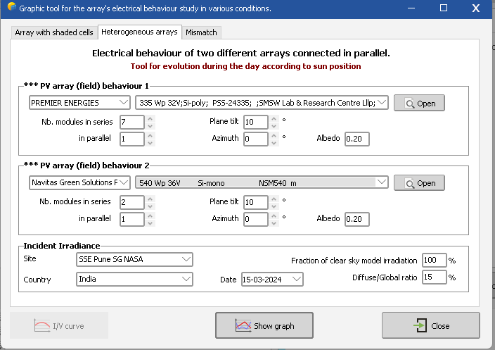
Hi, I wanted to simulate the mismatch losses when combining 2 different modules in series in the same string. PVsyst has the option to simulate the Electrical behaviour of two different arrays connected in parallel, but we wanted to simulate the electrical behaviour of different arrays connected in series. E.g. we wanted to check the mismatch loss when 9 x poly crystalline 335 Wp modules are connected in series with 2 x mono PERC bifacial 540 Wp modules. We understand this is not usual, as it would cause warranty voids from the OEMs but still if we just want to simulate this behavior, is there a way?

-
String configuration bug with Solaredge
Pranav Maheshwari replied to Pranav Maheshwari's topic in Problems / Bugs
Thanks @André Mermoud that worked! -
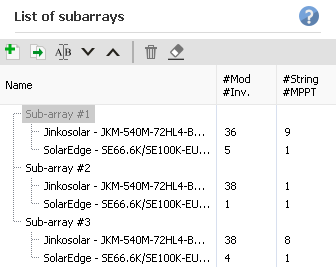
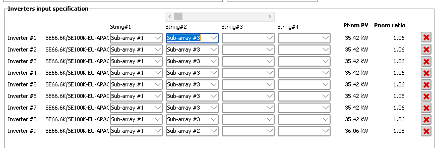
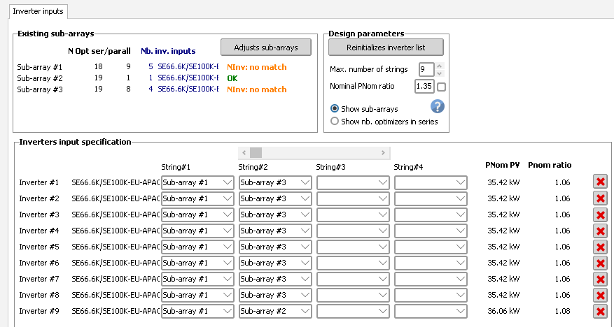
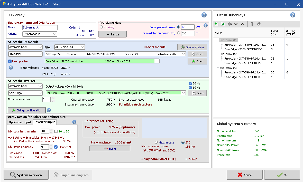
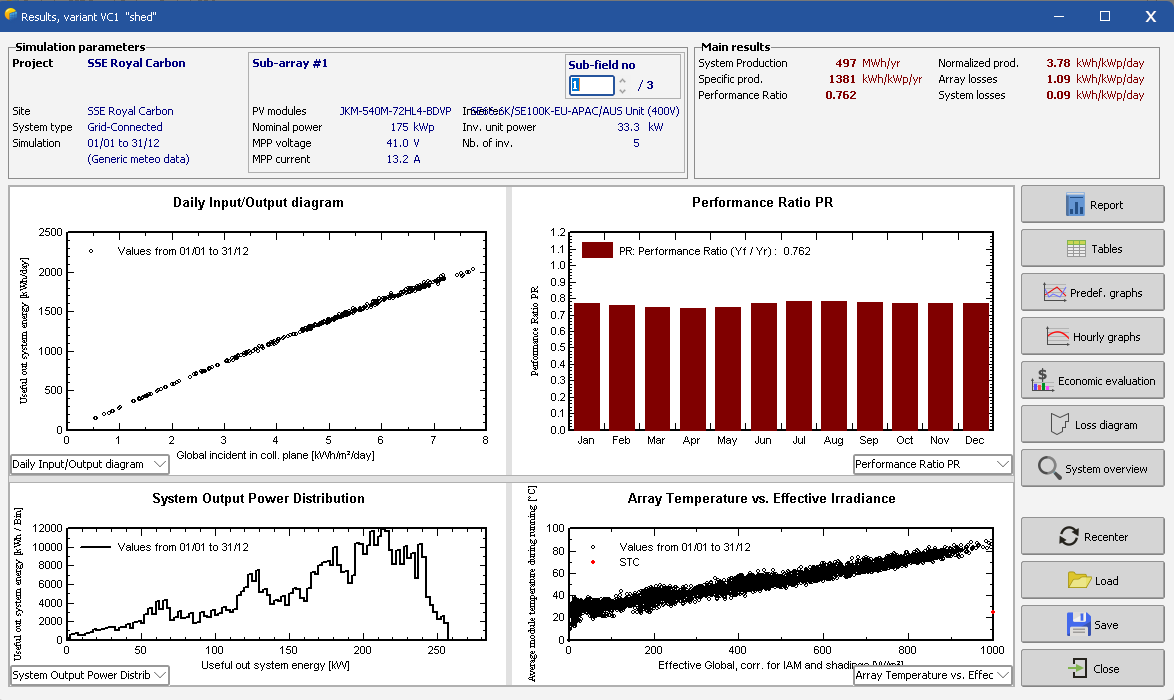
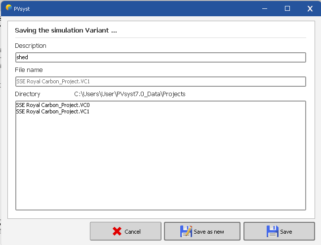
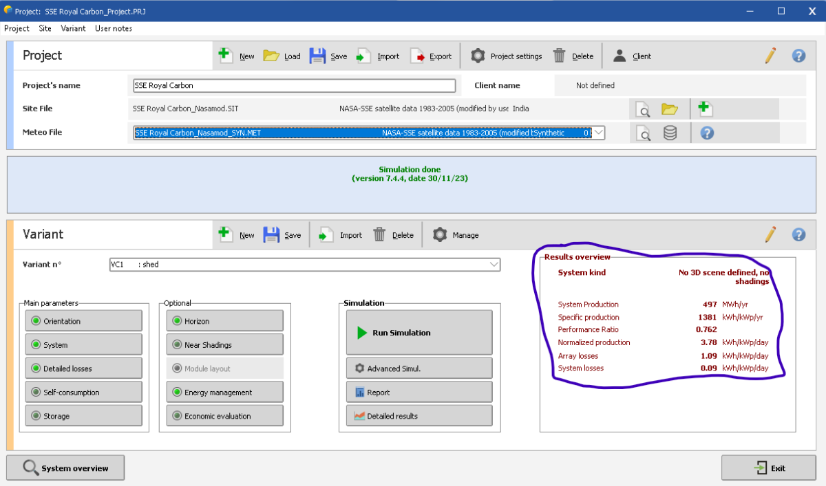
Dear Team, I am trying to simulate following system with S1200 optimizer and SE66.6K/SE100K-EU-APAC/AUS Unit (400V) with 750V input voltage: 9 strings of 18x2 modules: orientation 1 1 string of 19x2 modules: orientation 1 8 strings of 19x2 modules: orientation 2 Total no. of strings are 18, which I have divided in 9 inverters (2 strings / inverter) as follows: After closing this, there is no warning. Total no. of modules (666) and AC power (300 kVA) which matches the design After this, I enter the loss parameters and simulate, which is also successful: I also save the variant: And it shows the output also: Now i close the project, and when I again open the project & variant again, this error is shown: Why is this happening? Despite the simulation was successful and I also saved the variant, then also while opening it next time, its showing this error. I have checked all the system design and detailed losses data is still there, but not showing the o/p. I have to again open the string configuration and manually assign it to inverters then only this error resolves. But again next time when we open, the error comes back. Basically I feel that its not able to store the string configuration correctly and while recalling these errors come. I will be happy to provide more details for reproducing this issue which is happening to me.
-
Bifacial modeling with shading scene
Pranav Maheshwari replied to Pranav Maheshwari's topic in Problems / Bugs
Understood @Michele Oliosi But can I do as per the following method using multiple simulations: First simulation: without bifacial modelling with shading scene: using this I will estimate the shading losses Second simulation: using bifacial modelling considering unlimited sheds without shading scene: where I can put the approx. pitch and get an approx. bifacial gain I imagine that the actual bifacial gain will be actually more (for my case), than using an unlimited shed approx Please confirm if the above approach can also be used? -
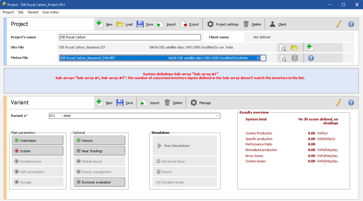
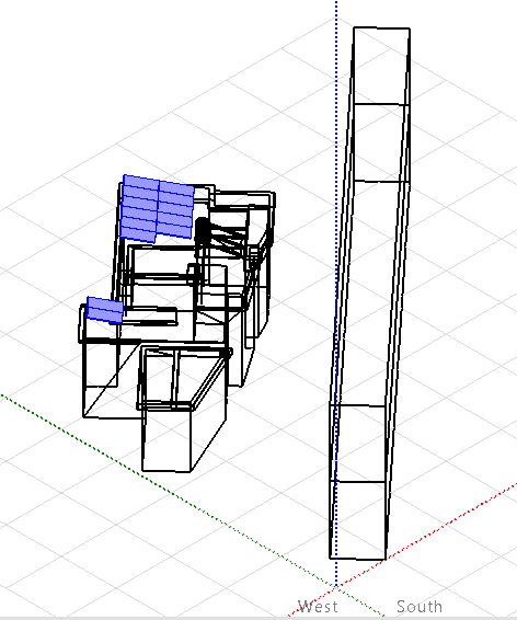
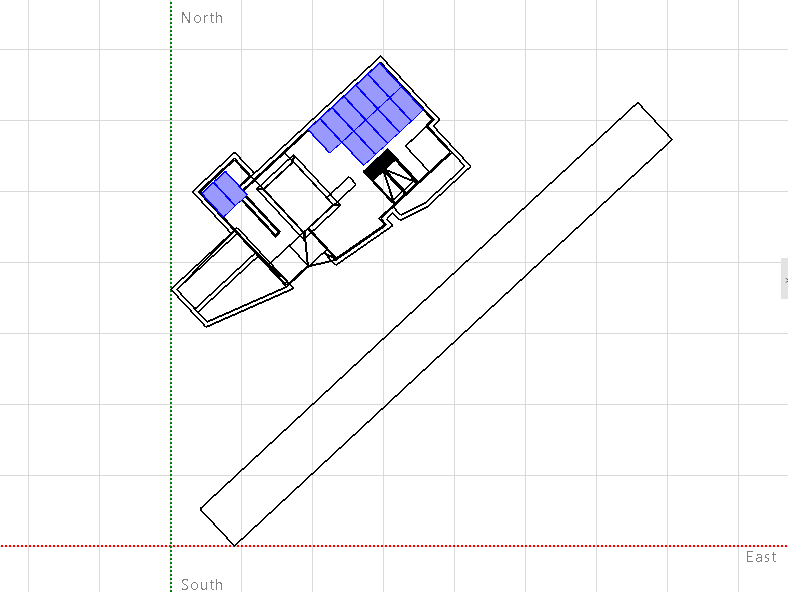
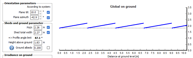
Hi, I want to simulate bifacial modules in a rooftop space, with shading elements So in order to simulate the shading loss, 3D shading scene is required. I also understand that bifacial modelling can only be done either using an unlimited sheds or unlimited trackers (2D geometries) as it computes view factors accordingly. Although my case is very different to unlimited shed model, but to approximate, I want to enter the pitch as per approx. roof space available on either sides of the PV table. So I want to enter the pitch and shed total width manually. Shed total width can be exact based on my table size, and for pitch I can enter an approx. number based on the space available on either sides of PV table. But it does not allow me to change these values manually (even if I change these numbers, it automatically changes them back) How do I fix this. So that I can estimate approx. bifacial gain as well as shading losses correctly. One temporary method is I do multiple simulations: One without bifacial modelling with shading scene: using this I will estimate the shading losses Other using bifacial modelling without shading scene and considering unlimited sheds, where I can put the approx. pitch and get an approx. bifacial gain I imagine that the actual bifacial gain will be actually more (for my case), than using an unlimited shed approx. Please guide!
-
@André Mermoud This is the same case, inverter contains 2 MPPTs, so thats why per MPPT Pmax would be 2.5 kW only
-
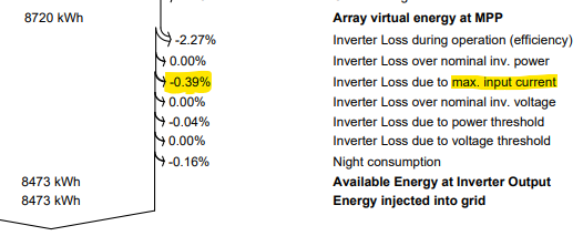
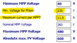
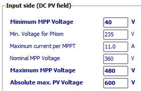
Yes, for the 2nd point, I did define the "VmppMin for PMax" as 235V and VmppMax as 480V. Automatically the max current per MPPT was set to 11A, which resulted in around 0.2-0.4% clipping loss associated with current. So although the cause of clipping is because of input voltage limit, but in simulation its reflected as current clipping because of how we've modelled. So this can be an correct approach right?
-
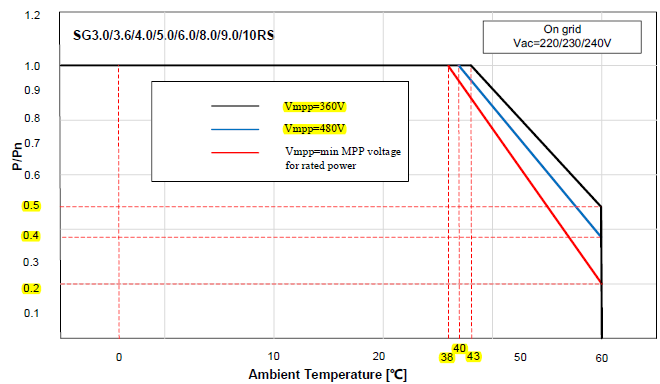
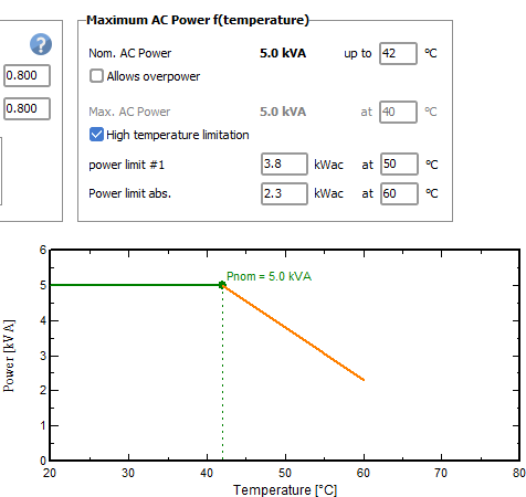
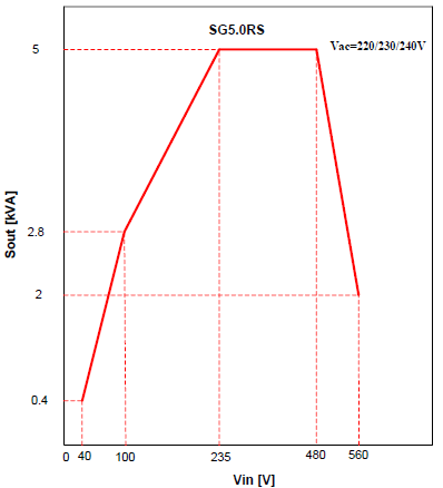
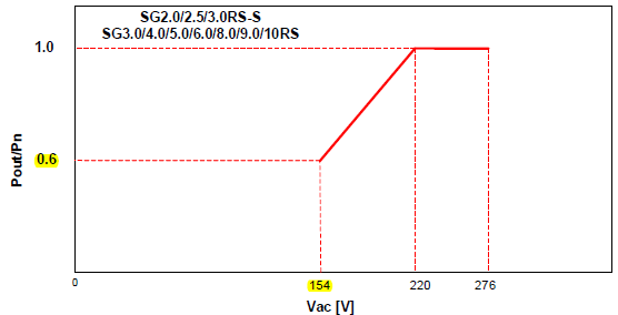
There are 3 inverter characteristics which I want to model in PVSyst: Temperature derating for multiple MPP voltage. Following is an example of Sungrow RS series inverters temperature derating profile at multiple MPP voltages: There is considerable difference in temperature derating for different MPP voltage, but we get to model only a single behavior. Power limitation as per input voltage: In the OND file, the MPP voltage range mentioned is 40-560V, but it can be seen from the above graph that full power is only attainable b/w 235-480V If we put the Min. Voltage for Pnom=235, then it automatically sets the Max current per MPPT at 11A (but actual mentioned in datasheet is 16A) Power limitation as per grid voltage: Although PVSyst assumes a constant grid voltage, so this behavior may not be essential to model. But if in future there is some variable grid voltage, specially for standalone systems based on loads, this will also become critical. Hope my problem statement is clear! Regards, Pranav