
André Mermoud
-
Posts
2075 -
Joined
-
Last visited
Everything posted by André Mermoud
-
 First of all, the definition of the "Solar Fraction" SF = EUser / ELoad is valid for Grid-connected systems. In Stand alone systems this is more complex: it is the Output of the PV system (EOut converter), minus the battery energy balance: SF = ( EOutConverter - EBattCharge + EBattDischarge ) / ELoad. The battery balance (EBattCharge - EBattDisch) includes the difference in SOC between the beginning and the end of the interval, and the battery losses. Therefore: - Over la short period, the Solar fraction is not relevant because of the battery SOC difference, - Over a long period, the SOC difference contribution becomes lower, but may still alterate the real value of the Solar Fraction. Now the battery losses are extremely difficult to evaluate, especially due to the variability of the effective capacity of the battery according to the Charge/Discharge rate: in PVsyst this is an approximation, which may sometimes lead to "positive" battery losses in some cases (depending on your load profile definition). This seems to be the case in your project, where the differences are very low (some few permille). See the Help https://www.pvsyst.com/help/physical-models-used/batteries/battery-model/battery-efficiency.html?h=battery
 -
Temperatures when simulating DC cable losses
André Mermoud replied to AhmadMick's topic in Simulations
In PVsyst, the cables temperature is fixed to 50°C at any time, supposed to be an "average" during all conditions of the simulation In the reality, the wire temperature is obviously not well defined: it depends on the wire mounting mode, the possible exposition to the sun, the current, etc... The sensitivity of the resistivity to the temperature is 0.39%/°C, for the copper as well as for the aluminium. See the help https://www.pvsyst.com/help/project-design/array-and-system-losses/ohmic-losses/metal-resistivity.html?h=resistivity NB1: in a next version, it will be possible to choose the temperature for any part of the wiring. In the present time, you can modify it in the advanced parameters. NB2: the wires temperature has nothing to do with the cell's temperature in the module. -
This parameter "Maximum current per MPPT" is indeed quite correlated to the "Minimum voltage for attaining PNom". See the help https://www.pvsyst.com/help/component-database/grid-inverters/grid-inverters-main-interface/grid-inverters-main-parameters/index.html#input-side-dc-pv-array Now if this is specified, PVsyst will apply this cutrremt limit during the simulation. But this rarely produces "Inverter losses due to current overload", as this limit is most of the time preceded (masked) by the Power overload limit. See the Help https://www.pvsyst.com/help/physical-models-used/grid-inverter/inverter-operating-limits.html If the limit is not specified, it is obviously not applied. Now this limit is not always well "understood" by the manufacturers who submit their data, nor well defined in the datasheets. Sometimes we have to add this information afterwards in the database.
-
PVsyst is a software for the study of PV systems. It is meant for the storage of PV energy, not the grid energy. It is not a suited for the simulation of any BESS systems on the grid.
-
What dou you mean by "Types of cables" ? The different types of cable (of a same metal) have in principle the same resistivity, and this is the parameter which determines the power loss. If you are talking about the installation mode: - The resistivity may indeed depend on the cable temperature, and therefore on the installation mode. - The main thing to be considered will be the current limit for a given cross section, which is specified in norms.
-
In the DC circuit (array of strings), the total wire length is indeed the lenght of the whole loop (this si mentioned just below "Please specify the total wire length for each circuit. " For the AC circuit, this is the line length (distance between devices).
-
mismatching night consumption at same AC capacity
André Mermoud replied to mohaned's topic in Simulations
Probably you have defined your transformer by a generic relative loss, i.e. proportional to the transformer nominal power. And this nominal power - evaluated by PVsyst on the basis of the PNomPV at STC, or the PNomac (this is your choice in the Project's settings) - has been changed in your different runs. This should not arise if you define an explicit transformer from the datasheets, the nominal power of the transformer will always remain the manufacturer's value. In this case the "generic" relative values will be updated as a function of this real Transformer nominal power. -
There may be new features in the version 8, which were not implemented in the version 7. Now for the modification of the Rshunt and Rserie values, this was a feature of the software which has been mpdified. In the version 7, when they were judged not quite correct, these values were updated to default ones. This is no more the case in the version 8.
-
The files created in the V8 cannot be used with the version 7.
-
You can add a battery in your database from scratch by using "Databases => Batteries => New". But you are strongly advised to choose a similar battery in the database, modify its parameters according to your own component datasheets, and save this as a new battery. For defining an hybrid system, you should choose the button "Storage" in the project's dialog, and probably choose the option "Self consumption" for your case.
-
No, in the present time PVsyst doesn't consider the charging of the battery from the grid.
-
Sorry, it is completely impossible that PVsyst changes these parameters by itself. Please carefully check that you are comparing the same variants. NB: You can always reload and install the old version 8.0.13 if necessary. Both versions may be used simultaneously.
-
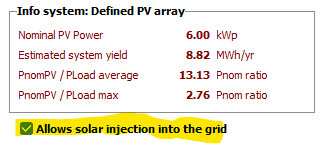
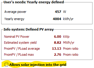
This is quite normal as you have defined a grid limitation of 1 kW (for a system of 200 kWp, 180 kWac). You can notice that the apparent value is 79 kVah, to be compared to a global delivery to the user of 224 MWh, i.e. 0.04%. Please note that you have the opportunity of completely forbid the injection to the grid when you define the self-consumption:

-
Battery being under-utilized in self-consumption simulation
André Mermoud replied to Dean O's topic in Problems / Bugs
Yes indeed, the battery model of PVsyst uses information which is not always present on the datasheets. Some datasheets are really very brief. When you have to define a battery by yourself, you are advised to start from an existing battery, and adjust the relevant variables (mainly technology, kind of battery, number of cells in series and parallel, internal resistance (check dafault), self-discharge (check default), lifetime (numbe of cycles), sizes and weight -
about PV module ageing parameters : Imp/Vmp contributions
André Mermoud replied to Chen's topic in Problems / Bugs
You can find some data about the current and voltage degradation in the works, namely, of the TISO in Switzerland. For example in this publication: https://www.researchgate.net/publication/256080133_TISO_10_kW_30_years_experience_with_a_PV_plant -
We obviously don't avail of detailed ageing data for a specified PV module. The average degradation rate itself is really not well defined. In the literature you can find a wide panel of values (0.3% to 1%/year). The PVsyst proposition of 0.4% seems a reasonable choice for usual modules. The specific mismatch effect due to ageing has been developed "theoretically" as a tool in PVsyst, without any experimental basis. We don't know any publication studying this problem in the literature. The hypotheses under this evaluation (Monte Carlo evaluation of the dispersion progress) are purely speculative. Therefore this model is obviously not able to take your particularity into account in a reliable way. You can probably take a lower value for the Isc/Vos RMS.
-
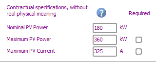
The PVsyst proposition doesn't take the maximum current into account. It is your job to check it in your final design. However the maximum current of a PV array is not well defined: the value corresponds to the STC (1000 W/m2), but if the inverter is specified for a given maximum current, it will limit the array current during operation, by displacing the operating point on the I/V curve. By the I don't see where you find that maximum current of 180 A. The manufacturer specifies 325 A in the PVsyst database: Your configuration of 15 strings of 25 modules of 650 Wp represents a PV power = 243 kW, i.e. a current of 238 A under 1020 V at STC.
-
Sudden Load Profile Spikes After Importing File
André Mermoud replied to Ady's topic in Problems / Bugs
Please remember that we are working in hourly values. And the thresholds according to the battery SOC may arise during the hour, so that the transition from an operating state to another one may arise during the hour. Therefore you can have a "Battery full" state at the beginning of the hour, and a discharge during the rest of the hour. However there is also a visual artefact because you are showing lines from the middle of hour to the middle of the next hour. In your first plot, at 13:30 you have unused energy, but no BESS discharge. At 14:30, you have BESS discharge, but no Unused energy. The intermediate lines don't have any meaning. -
First of all, the inverter's behaviour with grid voltage deviations is very rarely described in the datasheets, and probably different for each inverter. By the way, PVsyst doesn't treat possible Grid voltage variations along the time. This is not part of the input variables, and we really don't see from which source we could evaluate it in prevision simulations.
-
I don't see what you mean by "some modules are overlapping". For filling your field, you can do that manually by the mouse. But you can possibly use the option "Attribution automatique" (you have many options for doing this), and than correct what seems not suited for you, by exchanging/dragging the string attributions with the mouse.
-
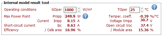
PVsyst doesn't provide a plot for this variation, because the Voc is not of big interest for the simulation. You can get the results of the model for any Irradiance and temperature conditions, in the PV module definition dialog, main page, "Internal model result tool":
-
The answers to your questions are fully explained in the help: https://www.pvsyst.com/help/project-design/array-and-system-losses/ageing-pv-modules-degradation/index.html?h=ageing https://www.pvsyst.com/help/project-design/array-and-system-losses/ageing-pv-modules-degradation/module-performance-degradation.html 1. - ISC dispersion has nothing to do with the datasheets information. Its nature is explained in the help. 2. - You can evaluate the effect of the Current and Voltage degradation weighting by yourself, by excuting several simulations. You will see that this is not very significant. 3. - When you have one only module, it is quite obvious that you don't have any mismatch loss. 4. - In the ageing process, the mismatch between "degraded" modules increases along the time. 5. - This is an input parameter. The global degradation is the sum of the individual PV modules degradation and the increasing mismatch.
-
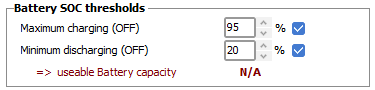
Sorry, I really don't understand your strategy. It is not the battery (or the Ecoflow) which decides when it starts charging or discharging, but the external conditions (user's needs or PV availability). Starting discharging at a given SOC doesn't make sense without a clear definition of the energy demand. PVsyst controls the the charging or discharging "autorizations" as a function of the SOC evolution. If you are discharging (drawing energy), the battery will stop delivering power when the SOC reaches the specified threshold "Minimum discharging". When you are charging, PVsyst will disconnect the PV production when the SOC attains the specified "Maximum charging". This may arise within hours, You have a part of the hour in one state, and another part in the other state.
-
Thank you for sending your project. However it doesn't show the same output as you have shown here: The message tells you that the maximum discharging power is highly undersized. Your load definition has many hours with a load demand of around 21.3 MW, including during night, and you limit the discharging power to 10 MW. When I specify 22 MW as a discharging power, as you did in your previous message, I don't see any error nor warning anymore.
-
The voltage drop of a PV array doesn't make much sense, as when the R*I² loss increases, the Pmpp will move on the I/V curve, and therefore the current will also be modified. PVsyst doesn't provide any guidelines for this difference between Power loss and Voltage drop, which depends on the I/V curve. We consider that the voltage drop is not defined, and of no interest in the case of I/V curves.