-
Posts
340 -
Joined
-
Last visited
Everything posted by Linda Thoren
-
Hello, You can read about how to adapt you PVsyst simulation to a floating system in the following post: https://forum.pvsyst.com/topic/1346-how-to-adapt-pvsyst-to-floating-pv-systems/
-

Orientations management version 8 on a hilly terrain
Linda Thoren replied to buffelkip's topic in Problems / Bugs
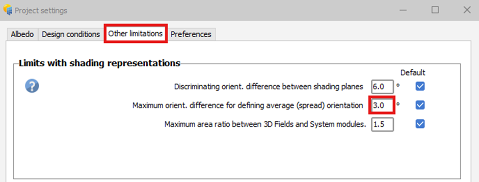
Hello, It seems to be linked to one of the new tolerances put in the new version that when the angle between your average orientation and at least one of your PV table is too high compared to the settings of your projects. To fix this error you need to increase this tolerance. From the main window of your project, click on "Project settings" at the top of the screen: Then you need to select the "Other limitations" tab and increase the value of the "Maximum orientation difference for defining average (spread) orientation" parameter: Once the value has been increased the error should disappear.- 1 reply
-
- hilly
- orientation
-
(and 1 more)
Tagged with:
-
Hello, The clearness index will be evaluated and compared with the clear day model for the same time period. Thus having only a few months of data will not be an issue. If you compare the data for 2025 with data for 2024, are they similar or are indeed the values for 2025 much lower?
-
Hello, Indeed the workflow would be to precisely define the coordinates for where the site, define the MEF file and run the conversion of the data. If PVsyst suggest a time shift, go back to the MEF file and define the indicated time shift and run the conversion again. If the issue persists, please send your data to support@pvsyst.com and we can have a closer look.
-
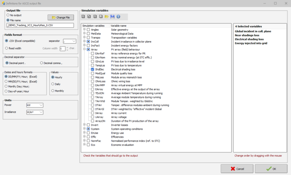
Hi, you can export an Output File with any relevant parameters through the Advanced simulation window.
- 7 replies
-
- shadings
- shading scene
-
(and 1 more)
Tagged with:
-
The multi-MPPT feature and how to configure different sub-arrays to precisely define your system is explained in the following youtube tutorial:
-
Hi, For hourly estimation of both the production and the specific losses, you can export an Output File with any relevant parameters through the Advanced simulation window. From the hourly/daily values generated, you can do any analysis in an external tool such as excel.
- 7 replies
-
- shadings
- shading scene
-
(and 1 more)
Tagged with:
-
the idea is the same for the limitation of maximum current per MPPT. The graphics in the system window is an approximation, not considering the backside production, though the simulation will.
-
Hello, The values used in the system sizing serve only as a guideline and provide an order-of-magnitude estimate, considering only the initial front-side production (excluding for instance losses and rear-side generation). For an accurate assessment of overload losses, you should run a simulation.
-
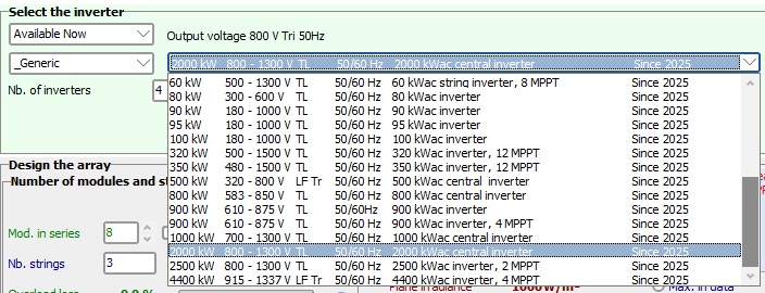
Among the Generic inverter in the database, you can find examples of central inverters. Here you see that there are no MPPTs. By opening the .OND file, you find this information in the Additional parameters tab.
-
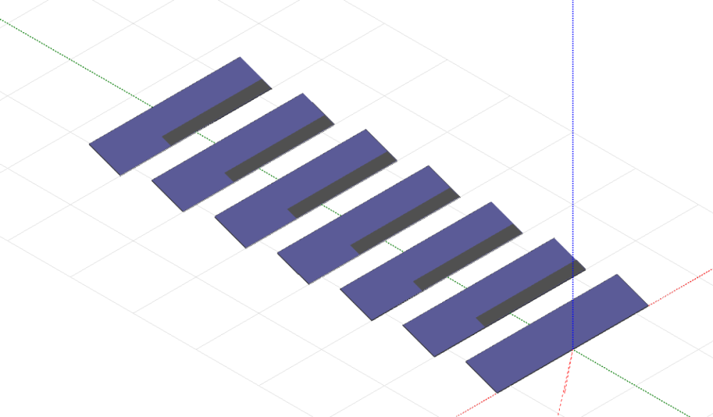
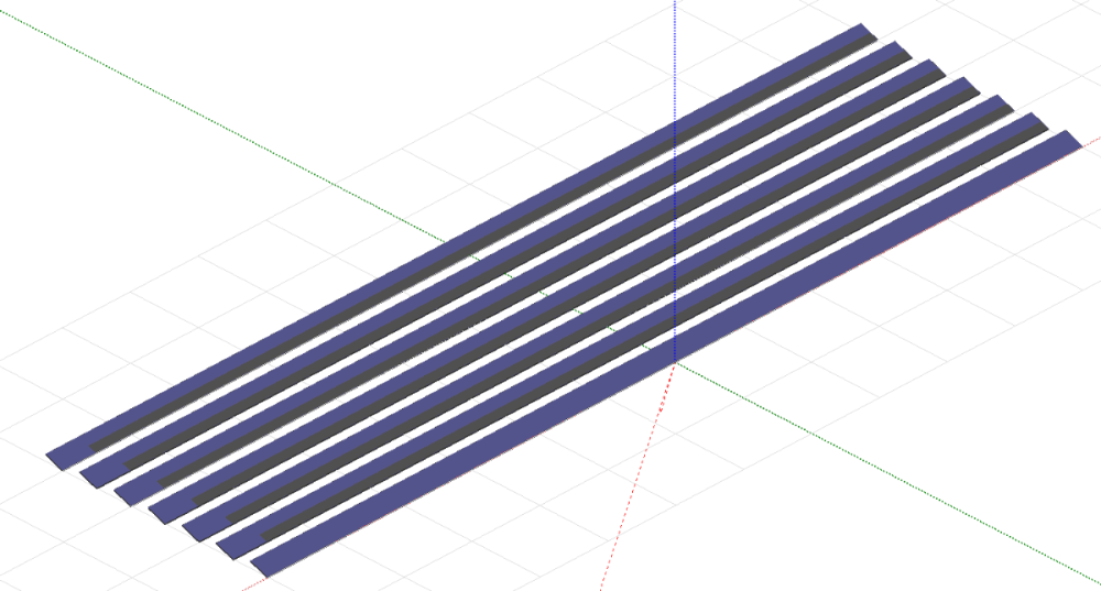
Indeed, the first row will not have any mutual shadings. For “unlimited” long tables, mutual shading can be applied uniformly across the entire row, allowing edge effects to be neglected. In the two images below, you can see an example, that for long tables, the impact of edge effects is limited to the lower-left corner and is therefore negligible. However, for shorter tables, this assumption becomes less valid.
-
Hello, In the database we unfortunately do not have a filter to sort out the central inverters from the string inverters. In PVsyst, the difference from a string inverter and a central inverter would be characterized by the fact that the central inverter do not have multiple MPPTs
-
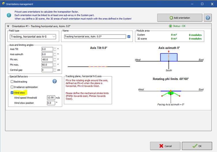
Hello, PVsyst does not consider any loss due to tracking inaccuracy and there is no general “other losses” parameter, though you could possibly add such a loss as a “soiling loss” for instance. If wind velocity is available in the meteorological data, you can simulate wind stow behavior. You would define a wind speed threshold, and if the wind speed during a particular hour exceeds this threshold, the simulation would be done for the defined wind stow position for that hour. This would normally result in a less optimized tilt angle and thus less production, though it will not directly appear as a loss in the loss diagram.
-
In general, the denomination of a given time interval in PVsyst is always defined as the beginning of this interval. This is valid for hourly, daily or monthly values. For meteo data, the time stamp is the time interval over which the irradiance measurement (or any other value) is averaged. For example, the time stamp 11:00 corresponds to measurements averaged between 11:00 and 12:00. When using irradiance models, the solar geometry should be calculated for an "average" of the time interval. PVsyst uses the middle of this time interval (in the previous example 11:30). Different weather data providers have their own definition of the timestamp and thus will be adapted to match the one in PVsyst.
-
Hello, A floating system is rather similar to a conventional PV system. Following forum post describes how you can adapt your simulation to a floating PV system: To start a PVsyst project, we have several tutorials in PDF and on youtube: https://www.pvsyst.com/wp-content/pdf-tutorials/pvsyst-tutorial-v8-grid-connected-en.pdf
-
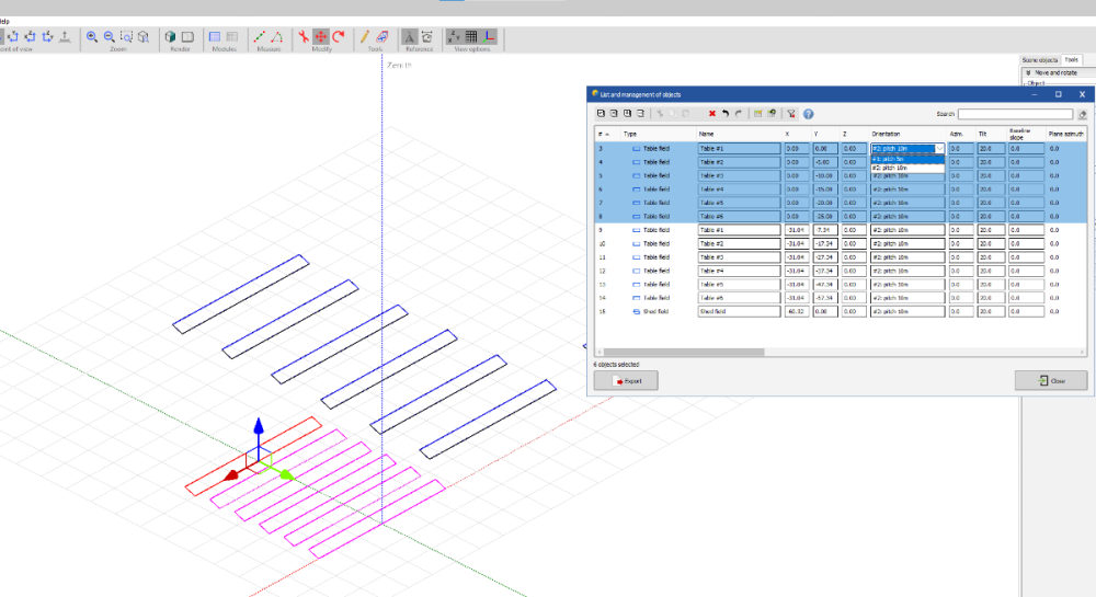
Hello, Yes, the zone tool will be improved in a future version. In the meantime, by defining a fixed tilted plane with the all the parameters you wish for your trackers (orientation, pitch, size etc.) and tick the option "Create tracking fields" (as you have done in image 4), the zone will be filled with trackers with the correct definition.
- 1 reply
-
- orientation
- 3d scene
-
(and 2 more)
Tagged with:
-
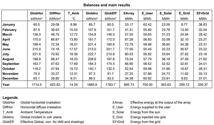
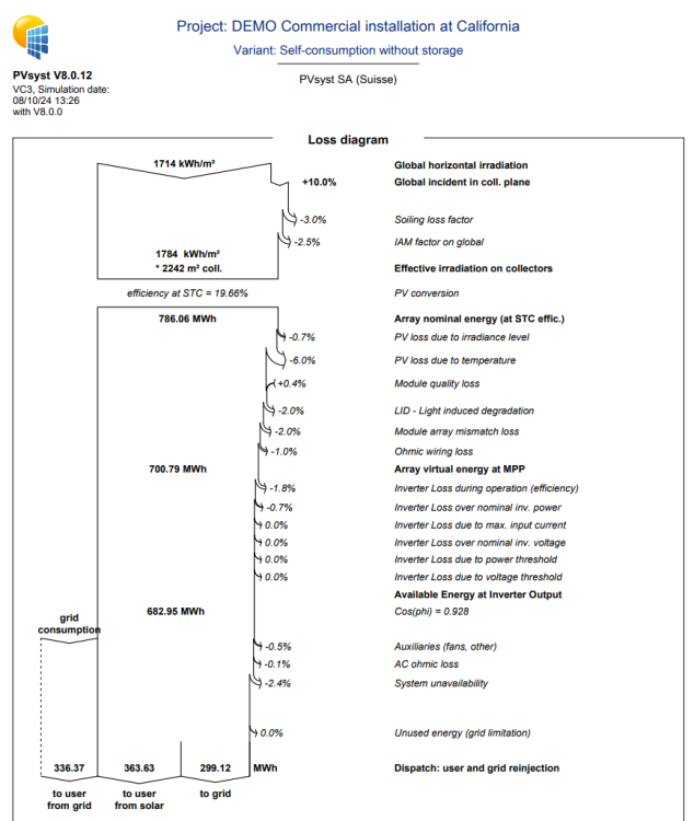
Hello Johann, The simulation and corresponding energy balance are calculated using hourly time steps. To determine how much of the generated solar energy can be self-consumed, the simulation must be run. For example, in the DEMO project “DEMO Commercial Installation at California” (VC3), the report shows: E_User: the total energy delivered to the user (reflecting the self-consumption profile), E_Solar: the portion of E_User that is covered by solar production, EFrGrid: the remaining energy that must be imported from the grid to meet the user's demand, E_Grid: any excess solar energy that is injected into the grid. These values are also illustrated in the annual loss diagram, giving a complete overview of the system’s performance over the year. Best regards
-

Daily generation profile Irregularities
Linda Thoren replied to JamesLenton's topic in Problems / Bugs
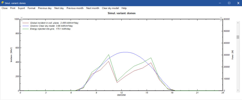
Indeed it seems a bit surprising that the global irradiance would be 0 for a few hours in the middle of the day, but indeed possible. Using another weather data provider, do you see similar drops in irradiance? If you import a weather file with missing data, these hours will be considered as 0 in PVsyst. -

Daily generation profile Irregularities
Linda Thoren replied to JamesLenton's topic in Problems / Bugs
Hello, To better understand the results, you can consider adding additional parameters—such as irradiance—to assess whether a drop in production is due to variations in weather data or other factors. In the Advanced Simulations, you also have the option to export hourly data as a .csv file, allowing for deeper analysis of any relevant simulation parameters. -
Dear Ihr, The Global horizontal irradiation is transformed to global incident in collector plane by using a transposition model. You can read more about the transposition model in the following PVsyst help page: https://www.pvsyst.com/help/physical-models-used/irradiation-models/transposition-model.html?h=transpositio The Global on collector plane from the Quick optimization box in the orientation window is based on the clear sky model at your site and is not the result of the simulation but serves as a quick optimization to get an order of magnitude of the irradiance in the collector plane according the chosen tilt and azimuth. The GlobInc in the report is the result of the simulation based on the hourly weather data.

