-
Posts
804 -
Joined
-
Last visited
Everything posted by Michele Oliosi
-

Array of trackers 3D scene defining N-S & E-W slopes
Michele Oliosi replied to JamesLenton's topic in How-to
@JamesLenton indeed, and glad that it worked ! -
@SPdesai Sorry it seems there was a wrong sign in my answer above. I have corrected it. The sign is positive. We are adding it back, indeed. Indeed, we expect that the rear POA sensor will not be shaded (mostly) by mounting structures or cables.
-

Array of trackers 3D scene defining N-S & E-W slopes
Michele Oliosi replied to JamesLenton's topic in How-to
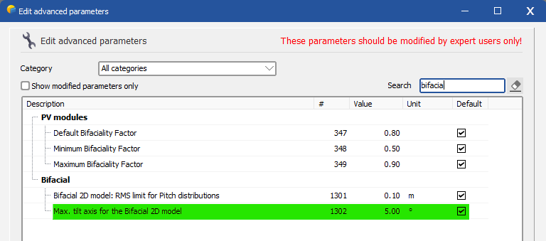
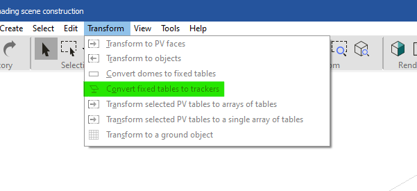
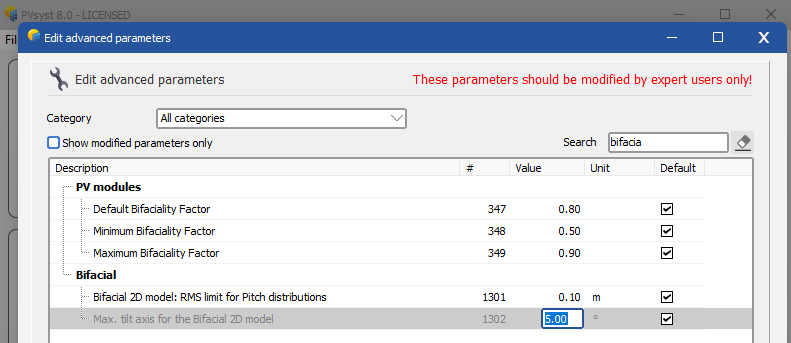
Hi ! Indeed, currently the backside and reflected irradiance modeling is quite picky. The idea is that the geometry it assumes is that of trackers on flat ground. The discrepancy between 3D scene and backside irradiance model therefore leads to this message, to warn users of the possible inaccuracy. However, there is no alternative model, and the approximation of flat ground is not too bad if the slope is only 5°. In other words: You can change an advanced parameter to ignore the axis tilt message: Home window > Settings > Edit advanced parameters: I think a good way currently is to build fixed tilt structures first and then use the "transform to trackers" option: This will ensure that you can use the row-to-row slope options which are available for fixed tilt arrays (if I am not mistaken). -
Pnom without temperature correction means nominal power, and not maximum power. So in your example it is relative to 320kW.
-
@NGS In case you have a warning due to the average axis tilt not being horizontal: you can override this error in the following way. Home window > setting > Edit advanced parameters: Note that this is only forcing PVsyst to proceed, but the backside irradiance model is still modeling things with a zero axis tilt (which generates a discrepancy with the actual orientation, and means there will be some uncertainty in the results).
-

PVsyst v6: Inconsistent Date Format in Hourly Output .CSV File
Michele Oliosi replied to kjs55's topic in Problems / Bugs
If you can, let us know what you find that would be great. -

PVsyst v6: Inconsistent Date Format in Hourly Output .CSV File
Michele Oliosi replied to kjs55's topic in Problems / Bugs
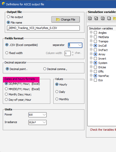
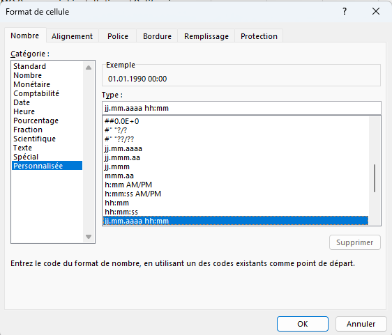
Hi, It's more likely a problem of compatibility of the PVsyst output with the regional format on your Excel/Windows installation. In PVsyst you can try changing the format and see if anything helps There are also more options on Excel, but I'm no expert there: -

Degradation in the First Year with LID losses
Michele Oliosi replied to Tanatip's topic in Simulations
If you follow Daniel's latter examples (1-0.4)/2 = 0.3%? Indeed here you would assume that the loss increases to 0.6% in one year so on average during the first year it is about half of that. But I am not sure if this assumption is good for all cases of LID. The value is certainly between (1-0.4/2) = 0.8% LID if it occurs during the first few hours, or 0.3% if you interpret the first year degradation value as a linearly increasing function without any further assumption. I would tendentially use the more conservative estimate of 0.8% LID. -

No import of meteo data, after selected and confirmed location
Michele Oliosi replied to Toni's topic in Meteo data
Hi, which version of PVsyst are you on ? This might be corrected by updating. -

Domes Simulation. How Pvsyst makes the domes simulation?
Michele Oliosi replied to Jorge Cobra's topic in Simulations
No, there is a problem with the components BeamInc, CircInc, etc. That's why the sum does not work. GlobInc is unaffected. -

Domes Simulation. How Pvsyst makes the domes simulation?
Michele Oliosi replied to Jorge Cobra's topic in Simulations
No, this is correct I think. Since this is GlobInc, not affected by the bug. -
Hi, this is likely because of the diffuse shading losses calculation. In version 7.4.8, you can check the details from the 3D scene window > Tools > Trackers diffuse shadings definition. If it is automatic, there is a chance that by ungrouping, PVsyst picked a representative tracker for the calculation (see the “central tracker” choice), which is not really representative. (2% losses is more realistic !) See https://www.pvsyst.com/help-pvsyst7/tracking_diffuse.htm or https://www.pvsyst.com/help/project-design/shadings/calculation-and-model/diffuse-losses-with-tracking-systems.html for the v8 help.
-

Domes Simulation. How Pvsyst makes the domes simulation?
Michele Oliosi replied to Jorge Cobra's topic in Simulations
Only the intermediate results are incorrect (...Trp, BeamInc and CircInc), the other results including the final production are correct already. -

Domes Simulation. How Pvsyst makes the domes simulation?
Michele Oliosi replied to Jorge Cobra's topic in Simulations
There was a bug that prevented variables ...Trp, BeamInc and CircInc from accumulating properly for a multi-orientation situation. We will update this for version 8.0.8. -

Mismatch Loss for Back Irradiance in Help Menu Example
Michele Oliosi replied to kjs55's topic in Suggestions
I confirm essentially what you mention. Thank you for the review 🙂 You are right, there are some updates to be done in the help. For the V8 it's simple enough, not sure whether we can change easily the v7 one. -
Indeed !
-
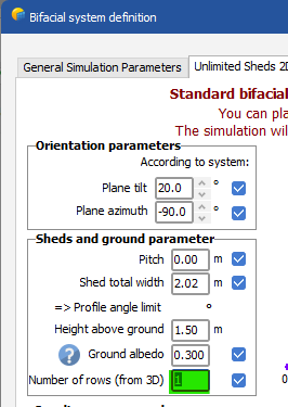
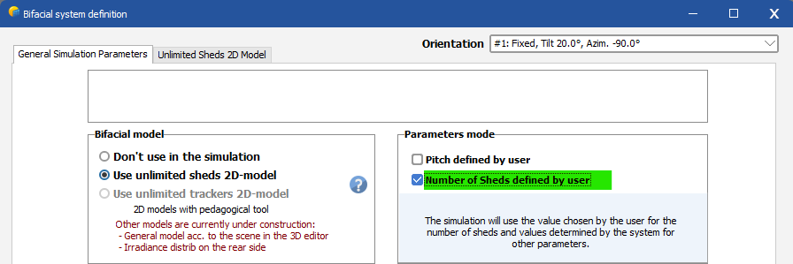
This post aims to present the main differences an user can encounter when using PVsyst 8.0.7 compared to PVsyst 8.0.6. Thin objects In versions 8.0.0 to 8.0.6, PVsyst did not calculate correctly the electrical shading losses for thin objects. This problem could be identified by inspecting the shading factor tables, showing inconsistent values when selecting “Thin objects table”: The calculation in PVsyst 8.0.7 now takes these properly into account. Electrical shading losses may be modified in your projects with thin objects because of this. Bifacial systems Several changes will affect projects with bifacial modules. No fundamental changes were made to the model, but default values and parameter labels have been updated. PVsyst 8.0.0 introduced the possibility of defining the number of rows and pitch used in the backside geometry model manually. Previous to that, the number of rows and pitch were automatically extracted from the orientation definitions, or from the 3D scene when available. This automatic evaluation was not always correct. For unlimited orientations, the number of rows used in the bifacial model is now forced equal to the number of rows in the orientation menu. Related fields in the bifacial menu cannot be edited anymore. See below in 'New Warning' for the behavior when opening a variant with simulation results that were using a user choice for the number of rows. Default number of rows The estimate for the number of rows has been improved. For example, in version 8.0.6, the number of rows returned the total number of trackers. This is now fixed. Note that with complex 3D layouts, this estimation could still be not fully representative of your system. This is why it is possible to override the number of rows manually. Reading PVsyst 7 or earlier simulation results Variants stemming from PVsyst 7 or earlier did not store the number of rows parameter. When reading the results in PVsyst 8.0.7, for variants where the number of rows cannot be determined retroactively, the report will show an “NA” note for the number of rows. If a new simulation is run, the number of rows will be set to the new default value. New warning A warning will be displayed when the user sets a non-default value for the number of rows in the backside geometry model. The PVsyst estimation for the number of rows is based on the 3D scene layout when available. With complex 3D layouts, this estimation could be not fully representative of your system. In such a case, this warning can be ignored. For the rare cases, where a variant with an unlimited orientation contained a user choice for the number of rows in the bifacial model, this warning will also appear if the variant contains simulation results, to make sure that the report and results correctly reflect the settings that have been used for the simulation. Since this option is not available anymore in V8.0.7, it is not possible to change the number of rows in the bifacial window. However, when running the simulation again with V8.0.7 the number of rows will toggle back to the default value, which is the number of rows defined in 'Orientation'. EW axis and NS-frame trackers When the azimuth of the axis was not zero, shadings were not properly calculated. This meant that the “Near shading losses” were not reliable. This has been corrected. Grid limitation and trackers In versions 8.0.0 to 8.0.6, a bug when combining grid limitation and the tracking algorithms “irradiance optimization”, “wind stow” or "seasonal tilt" prevented these algorithms from being properly applied. This has now been fixed. This may increase transposition gains in your variants, as irradiance optimization now corrects the tracker motion to maximize irradiance properly.
-

Shading loss factor without 3D Scene
Michele Oliosi replied to Umut's topic in Shadings and tracking
No, sorry, that is not possible. This would invalidate all hourly results. -
Okay ! Then yes I would divide them by the related maximum power. DC cabling loss -> DC capacity AC cabling loss up to transformer -> AC capacity AC cabling loss transformer to POI -> transformer capacity
-

Weird Thin Objects Electrical Shading Factor in PVsyst 8.0.6
Michele Oliosi replied to AutoRob's topic in Problems / Bugs
The thin objects shadings does not work in 8.0.6. Sorry for the inconvenience, we noticed this only recently. This should be patched for version 8.0.7.

