
Michele Oliosi
-
Posts
811 -
Joined
-
Last visited
Everything posted by Michele Oliosi
-

Diffuse on ground / diffuse ground fraction in bifacial
Michele Oliosi replied to ynesse's topic in How-to
In PVsyst, the diffuse component is considered isotropic. Therefore, it is sufficient to know for every point on the ground what portion of the sky (top hemisphere) isn't covered by other tables. This can be integrated for all positions on the ground. This fraction is purely geometrical, and is then to be applied to the total diffuse irradiance. -
Minimum height above ground - Tracking system (bifacial model)
Michele Oliosi replied to JGM's topic in Suggestions
The following parameters : Axis azimuth / Phi min / Phi max / Uses backtracking / Pitch / Shed total width, in the bifacial window do not affect the simulation in any way. They are in this window for educational and studies purposes only. (See the text in dark red at the top of the window). The default values taken for the simulation (e.g. 44°) are taken directly from the 3D scene, if it exists, or the orientations window whenever you are using an "unlimited" orientation. My first guess is that 44° is the effective axis azimuth once you take all the trackers in your scene into account. Do you happen to have different patches of trackers with different azimuth? The value 44° should correspond to the axis azimuth value found in the orientation window. Could you check that they match ? Thank you for the suggestion, it could be a nice addition. At the moment we only work with the axis height above ground, because that would be specified once you choose a specific tracker model. -
Hi this peak is due to the clipping, indeed any power above the grid limitation or inverter nominal power will be clipped to the value, the generation distribution is therefore biased towards values close to the clipping value. There is therefore probably nothing wrong with your system. However at the moment the scaling of the plots is automatic in PVsyst, and there seems to be a bug on that level. At the moment there is nothing that can be done to change the scale of plots when printed in the report, unfortunately. We'll be looking into how to improve this situation...
-
Should be out in the next patch ?
-
Hi, While the injected current is not an output in PVsyst, given E_Grid and the specific HV voltage, you can easily calculate the average current during each simulation hour. Just use the Advanced simulation > Output file tool to output E_Grid for each hour as a csv.
-
Did you have any unavailability time periods affected in the detailed losses parameters ? This may be the reason for this.
-
Modeling two different module using One central Inverter
Michele Oliosi replied to mohsinsanaullah's topic in Simulations
No in principle the total inverter power is maintained. -
If you consider the "usual" sun path at equator, basically the sun will rise quite to the east and go up in the sky quickly and then go down to the west. The time spent by the sun around azimuth 0 or -180 is really shortened, with respect to a sun path at higher latitudes, with the sun being lower on the horizon. Essentially you want to maximize the time your sun is facing the modules, i.e. the azimuth and sun height match the plane orientation. If you are close to the equator, and your POA is north / south or south oriented, the time spent with matching azimuth will be quite low. However with a POA facing east or west the azimuth will match quite well for about half the day.
-
The view factor is calculated with the following idea: given a point on the ground, what is the part of the top hemisphere that corresponds to the back side of the modules. Indeed some of the light reemitted reflected by the ground will go towards the sky, other towards the structure, maybe some shading objects etc. With the view factor we are interested what is the proportion of reemitted light that actually goes to the back of the modules and not to some other direction. Now, imagine that the size of the tables with modules varies. Depending on the size and spacing of the tables, for a given point of reemission on the ground, the fraction of light rays that reaches the back of the modules will vary. In short, the point on the ground may "see" more or less of the back of the modules.
-
Hi @Ronald you can export a CSV file via the project window > Advanced simulation > Output file and then re-running the simulation from the Advanced simulation window. See https://www.pvsyst.com/help/output_file.htm for more details.
-
Hi @NoamD, Thank you for the feedback. In this case, I see that the simulation version is 7.2.3. There have been many corrective patches since then, so I would strongly suggest you update to the latest version, or at least to the latest version 7.2, i.e. 7.2.21. This will allow you to obtain more accurate results, and I believe this specific warning message should be resolved.
-
Thanks @kjs55 indeed that makes more sense. @MarVF6 indeed at the moment there is no native way to modify several orientations through the batch mode. In the medium long term we should be able to develop the feature along this direction, but to my knowledge it will take some time.
-
Electrical shading losses in versions 7.3.X
Michele Oliosi replied to Michele Oliosi's topic in Shadings and tracking
@Haus Yes I believe it is due to this new calculation. The overhead poles and wires probably cause very little shadings overall. Some of these situations were neglected in version 7.2.21, and are not neglected in version 7.3.2 anymore. I would suggest trying to change the advanced parameter controllling the cell width to 0, as in the screenshot above, and then making sure that the thin shading fraction is low enough. However depending on the original amount of shadings I believe the electrical shadings may increase even more. If you can let us know the results that would be very valuable. If the discrepancies are too high, I would invite you to send us your project at support@pvsyst.com (exported via the main window > File > Export project), this is the best way for us to check in details on a case by case basis. -
Is it possible to put a specific String on a specific MPPT-Input?
Michele Oliosi replied to Katinka89's topic in Simulations
In the system window, if you activate the "multi-MPPT" mode, you will be choosing a number of MPPT inputs for a given sub-array. In PVsyst, it is common practice to group MPPT inputs (or inverters when disabling "multi-MPPT") that share the same properties into a sub-array. You can create a sub-array with one or several MPPTs that will receive strings with the same shading situation, for example to prevent mismatch. If you do so, when you are using the module layout, you should be able to assign the corresponding modules to that specific sub-array. In the system window, do not forget to implement the "power sharing" between sub-arrays that belong to the same inverter configurations. -
Hi you can have a look at https://www.pvsyst.com/help/ageing_general.htm The STC maximum power point average degradation will be the same no matter the modules, if the ageing rate is the same (%/year). However, since different modules have different one diode model parameters, the same ageing rate may lead to different behaviours for conditions such as temperature behaviour or low-irradiance behaviour. Then, if the plant has the same string layout, the mismatch degradation calculation will lead to the same mismatch due to the degradation (another loss that is due to ageing). But different stringing may lead to differences in the mismatch.
-
Change in far shading losses going to version 7.3
Michele Oliosi replied to laurahin's topic in Problems / Bugs
Hi Laura, Thanks for the feedback, we'll be looking into the issue, it was not a bug known to us yet. -
RMS - receiving different mismatch losses with same inputs
Michele Oliosi replied to Mara's topic in Simulations
Hi this tool uses monte carlo for the evaluation. Basically random trials are done every time. The values will only converge with many trials. -
No sorry, PVsyst only works with hourly simulation steps. This is why PVsyst can import sub-hourly data but will always eventually summarize the data as hourly data.
-
@sujinlee If you have a 3D scene, in fact you do not need to use the "unlimited sheds" orientation. The "unlimited sheds" is a special orientation that allows you to make an rough evaluation of mutual shadings when you don't have a 3D scene at all. However, if you have a 3D scene, using it is the preferred option. The 3D scene will allow PVsyst to compute mutual shadings and shadings from other objects accurately. Nota bene: whenever you have a 3D scene that is active, you should choose the orientation "fixed Tilted Plane", and not "unlimited sheds". You do not want to count shadings twice. NB2: The orientation in "fixed tilted plane" will correspond to the average orientation of the planes. When using unlimited sheds, you can have only a single value of pitch: this is because it is a rough evaluation only.
-
The most accurate is the second option. However if the system is too intricate to split into two (e.g. two orientations on the same inverter), I would suggest to group all modules as one orientation.
-
Energy loss diagram, bifacial (detailed results) (Ver 7.3.1)
Michele Oliosi replied to HLubke's topic in Problems / Bugs
Thank you very much for reporting this. I haven't been able to reproduce the error on a simple project. Could you give us some specifics on the project? I'd invite you to send us your project (Main window > File > Export project) at support@pvsyst.com. -
Import PVcase Tracker Layout with Gaps
Michele Oliosi replied to audlau's topic in Shadings and tracking
Indeed, you cannot establish a gap between each string length in a PVsyst 3D table or tracker. Only a homogeneous gap between each module, and an extra gap for the torque tube / longitudinal central spacing (central gap) if needed. I would suggest splitting the tracker into three trackers, already in the PVcase design. Is that an option for you ? -
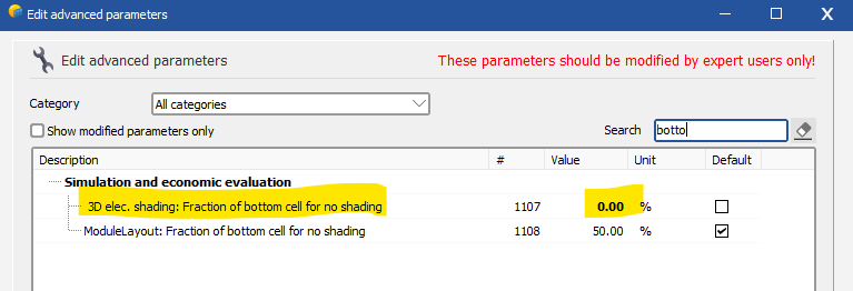
Minor version 7.3 has introduced a new way to compute the electrical effect of shadings, whenever only the cell at the bottom of the modules or submodules is shaded. The goal of the update is to better represent the actual behavior of these electrical effects: if one gradually shades the cells the are at the bottom of a module or submodule row, the electrical shading loss should quickly increase linearly until a plateau is reached (they are at their maximum value) once the full cell width is shaded. Compared with version 7.2.21 this tends to decrease the electrical shading losses. However the discrepancies have been more marked in certain cases. In practice: In the "module layout" mode: the new bottom cell evaluation is performed for each submodule independently. This is the most accurate way to model this effect in PVsyst, and we are confident that update 7.3 has improved the overall accuracy of the evaluation. In the "according to strings" mode (fast and slow): the bottom cell evaluation happens globally for the whole scene. An average shadow height is evaluated and compared to the width of the bottom cell. This approach has been extensively tested in regular setups, and should be more accurate than 7.2.21 for regular arrays with many rows, on a single orientation. However, this approach tends to underestimate the electrical shading effects as soon as irregularities are added, e.g. other shading objects, being on a complex topography, or using different orientations. This unfortunate effect has been discovered recently and a correction is being studied. The new behavior can be circumvented, see below. When using the "unlimited" orientations, with electrical effect activated: this situation is ideally regular, we therefore expect that new corrections yield a more accurate result (see caveat just below). A less common error affects projects using the unlimited orientations and half-cut modules in landscape. At the moment the bottom cell evaluation is incorrect for this case. We recommend using version 7.2.21 for this specific case. Workaround for the "according to strings" mode: To revert to a behaviour that mimics version 7.2.21, users can modify the parameter "3D elec. shading: Fraction of bottom cell for no shading" to 0 %. Note that in certain cases, the behaviour of 7.2.21 cannot be replicated. This is for example the case whenever shades cover only a very small fraction of the area, or with thin shadings. The second parameter in the screenshot can also help mimic version 7.2.21 for the "module layout" case. We however consider the new calculation better than the previous.

-
PVsyst will not calculate like that. PVsyst will simulate the following: The reason for the difference between warning in one case and error in the other is that (for the warnings only) PVsyst in the first case does only a rough evaluation using the total Pnoms, it doesn't separate the two types of inverter. If you still want to proceed, you can change the threshold for activation of the error. It is found in the project settings, you can increase the value 3% to a higher value.
-
0) right 1) Yes, in fact we iterate the formula twice, because the efficiency depends on the temperature. 2) U = Uc + Uv * WindVelocity, and the values are kept as entered by the user. 3) usually, but it may be different (it is defined in the module, you can find it under "Additional data" / "Secondary parameters" 4) GlobEff 5) efficiency is the module PV conversion efficiency, not jut 10%. See point 1, we start with the efficiency at ambient temperature, and then iterate the formula.