

dtarin
-
Posts
873 -
Joined
-
Last visited
Posts posted by dtarin
-
-
You define the ac losses. Enter them according to your design.
-
Your AC losses are probably too high. Is 3.2% accurate? I dont think I've ever seen a plant with AC losses that high.
-
I'd like to re-suggest the ability to define a monthly soiling profile in batch simulations. This will facilitate running time-series analysis for soiling losses.
-
Not from what I've seen.

-
Yes, or the crosshairs.
-
Thank you.
-
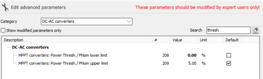
In general, it looks as though PVsyst has a minimum built in, irrespective of what is stated in the OND file. EArrayMPP must be greater than 0.5% of Pnom, and I think there might also be an irradiance requirement, although I can't find the details at the moment. Changing the setting below did not change behavior in my test. Results were pretty consistent with the 0.5% requirement, but there were four hours where there was inverter output below this.

-
-
Change the tilt to -90 or 90 after it has been created and placed into shade scene.
-
It is common to install Tamb and Wspd sensors ~2m above grade (for 2P systems maybe higher). ASCE measurements for wind are taken at 10m height.
-
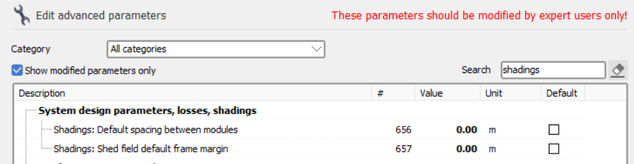
This might be because by default you have defined module spacing in the X direction, but the file you imported does not include this (because it is 1 in portrait). So PVsyst first imports the correct orientation and dimensions, but after saving, closing and reopening, it is applying the default module spacing. Since the X dimension + X spacing is greater than the tracker dimensions originally imported, PVsyst is automatically adjusting. It has in my experience changed it to landscape when this occurs, I haven't seen it change to 0 in portrait before.
Go into advanced settings and change the following. @Stéphane Degré If PVsyst were to identify 1P vs 2P, it could ignore X spacing in the former.
-
Hello,
Similar to the Aging tool where we can save each year as a new variant, it would be great if we could do the same for batch runs.
-
It may have run, but did you check that the results in the waterfall reflect a change in pitch? It's been my understanding one needs to use an array of trackers for this to work.
-
This should be under "how to" or another forum category fyi.
If you are using a shade scene which has individual trackers (like from a PVC import), you cannot vary pitch in batch mode. Varying pitch in batch simulations only works on regular arrays (in shade scene, go to create > array of trackers) or using unlimited sheds. If you have multiple arrays of trackers, you will likely need them all at the same X coordinate as well or with enough spacing that they wont run into each other. If you're running GCR analysis, these two methods should be sufficient. When using the array of trackers, specifying the tables in backtracking management is not needed.
-
Export the 8760 and create a custom weather file then reimport.
-
rotate 180 degrees
-
Another place to check is under advanced parameters setting the default value. But looking at it from another perspective, rounding in either direction is a difference of < 0.05% at the meter, and a second decimal might imply some level of precision that may or may not be there.
-
Have you defined LID only under detailed losses? If you define LID in the PAN file, it should stick; used 7.2.21 to test. Select "take value from module spec" in detailed losses.
-
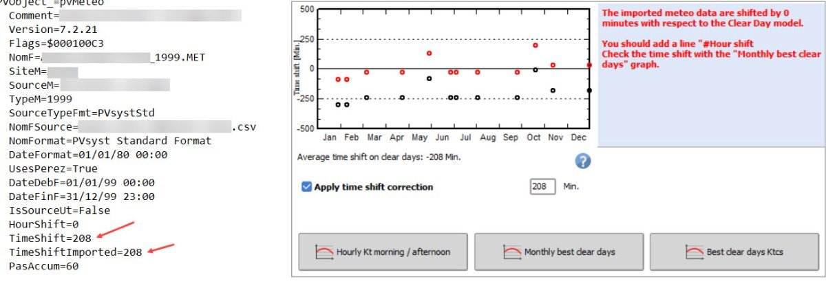
I have imported data and added a timeshift definition in the weather file. It shows graphically under the meteo file, but it says that the data is shifted by 0, even though it is defined and showing. Is this an issue with the software? Running 7.2.21
-
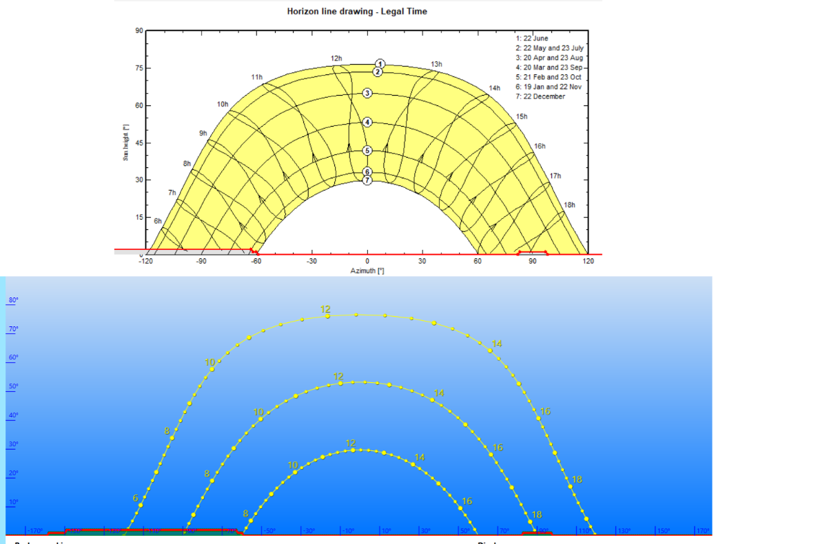
This looks like it is showing an "effective" azimuth. You see there it shows nominal at -100.3, but due to the terrain for the site, PVsyst is calculating something different. This is typical. When you have certain topography, you will not have the same azimuth/tilt as the nominal.
-
When running simulations with fast enabled under shading, PVsyst uses the shading table to calculate shading losses. When selecting slow simulation, if I understand correctly, it is calculating shading losses hourly from the shade scene. If the latter is correct, when first initiating a simulation with slow method enabled, can PVsyst skip generating the shading table if it is not used? This would reduce the time for the simulation. Users can always go back and generate a table later if they want.
-
Example: 700kWdc, 650kW inverter nameplate @ Pnom, 600kW grid limit
Pnom ratio = DC capacity/Inverter Pnom: 700/650
Grid limit Pnom ratio = DC capacity/Grid limit: 700/600Generally, the grid limit is less than the inverter nameplate, so the DC/AC ratio is higher here. In the PVsyst report, the Grid lim. Pnom ratio is found under System Summary, and the Pnom ratio is found under PV Array Characteristics.
-
That is correct.
-
On 3/5/2023 at 7:53 AM, Moataz Yassin said:
So does this voltage calculated based on the Temperature only or does it consider the irradiance at this temperature also ?
because at the low temperature the irradiance is very low so although the voltage increase due to low temp there is an opposite factor that limit this increase which is the irradiance and this data is from the TMY file
and regarding the lowest temperature do i have to insert it in the project setting or the data can be used automatically from the TMY file i inserted ?
Irradiance is not considered when calculating string lengths - Module Voc_max = Voc x [1 + (Tmin - T_STC) x (Tk_Voc/100)]. Temperature has a small impact on current, but it is mostly voltage that is affected.
One note to make here, a TMY file is an average of expected conditions and may not be suitable to define a "worst condition" scenario. Time series data over a historical period would be more informative.


Pitch vs Backtracking Pitch
in Shadings and tracking
Posted · Edited by dtarin
Have you defined a frame size?