

dtarin
-
Posts
873 -
Joined
-
Last visited
Posts posted by dtarin
-
-
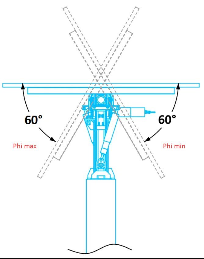
Phi is the variable to change for this exercise. Phi_min = Phi_max in the batch parameter file to simulate a tracker at angle. Tilt and azimuth should not be changed.
-
You cannot simulate SAT with fixed tilt. You need two separate variants. Yes, you can simulate MV and HV losses.

-
If your site is that large (GWs I assume here), you're better off running them in separate variants. Also with a site that large, you may not need to model the entirety in the first place, as long as you have a scene that is representative of the overall site.
-
It does not, trees are solid, static objects.
-
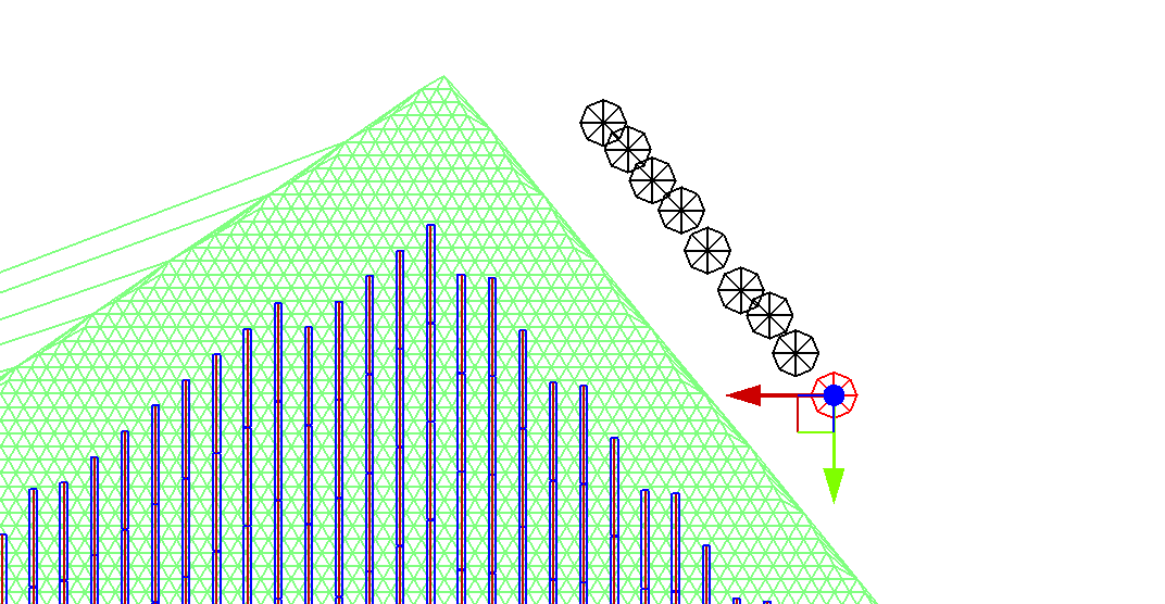
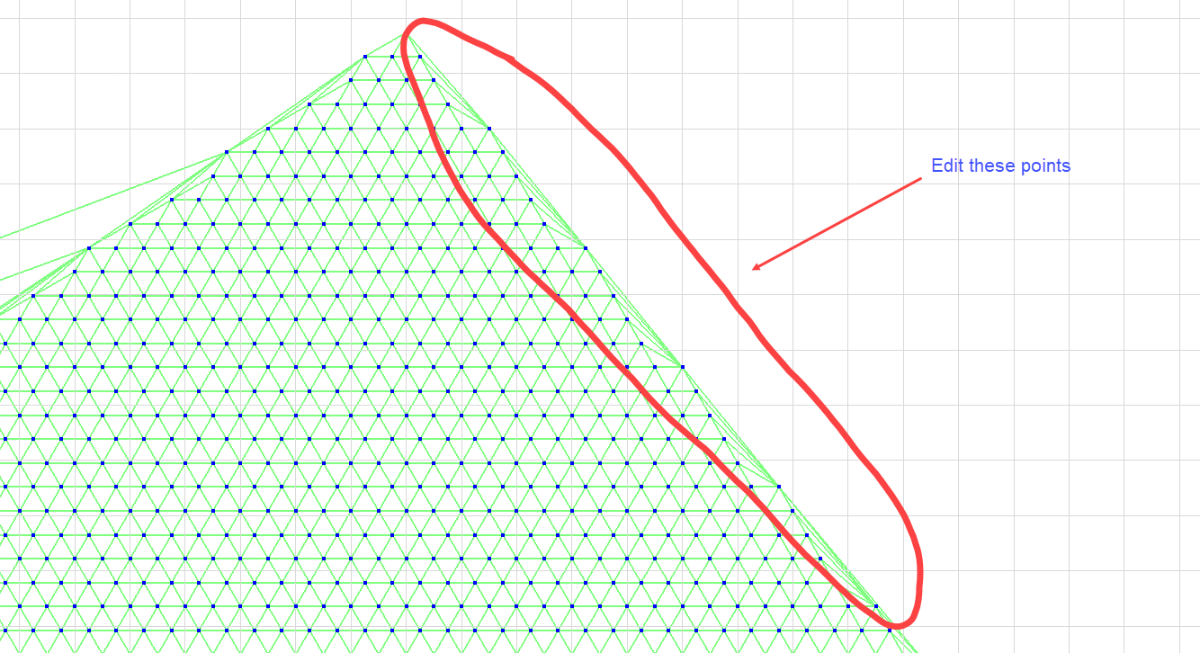
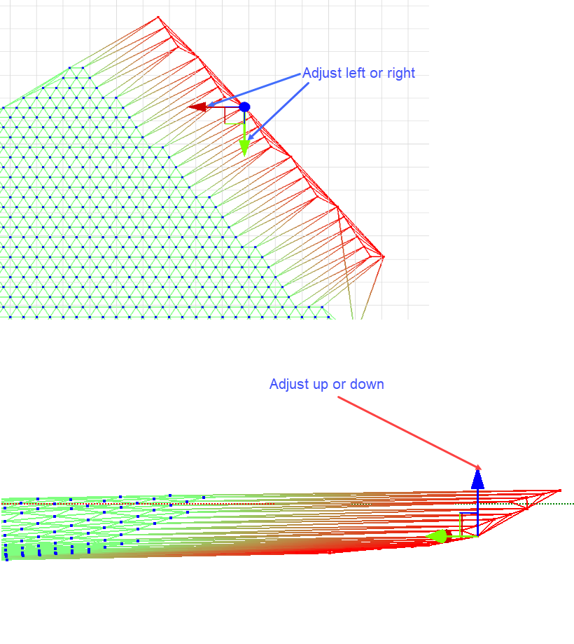
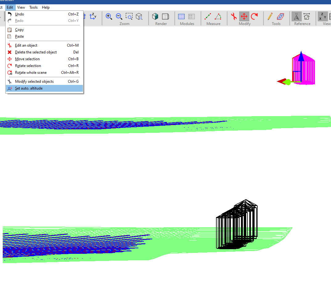
If your trees are over the terrain, you can place them onto the terrain with any offset desired using edit > set auto altitude. If your terrain surface is limited, and you need to add trees that are outside the boundary, then you can manually adjust the edges of your terrain by moving points individually in the X, Y, or Z direction (you can select multiple at once, it is not restricted to a single point, in case previous statement was misleading). After the terrain surface is adjusted, use auto altitude on all objects.
-
-
You need an image of the modules on terrain, and then import and scale the image into pvsyst. You can then visually align the modules imported from CAD and the ground topography from Sketchup to the imported image.
-
Include GHI. Day 1 could be a cloudy day.
-
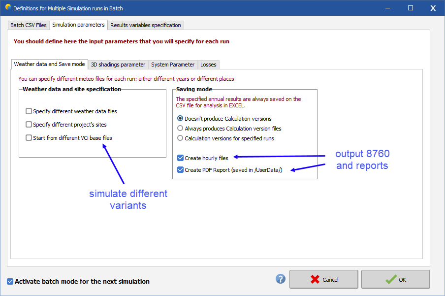
This can all be done with batch simulation. Advanced simulation > Batch simulation. Prior to running the batch, set the output parameters under Output File, and make sure File name is checked under Output file. You don't need to give any specific name, just have this checked (you will define the output file name in the batch parameter file in the next step). Then proceed to Batch simulation to set the parameters and configure the batch file.
-
-
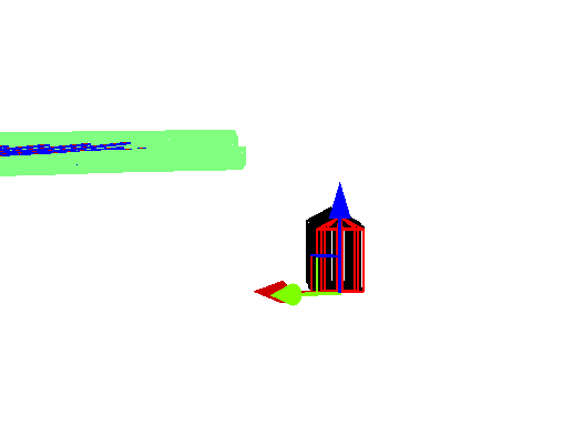
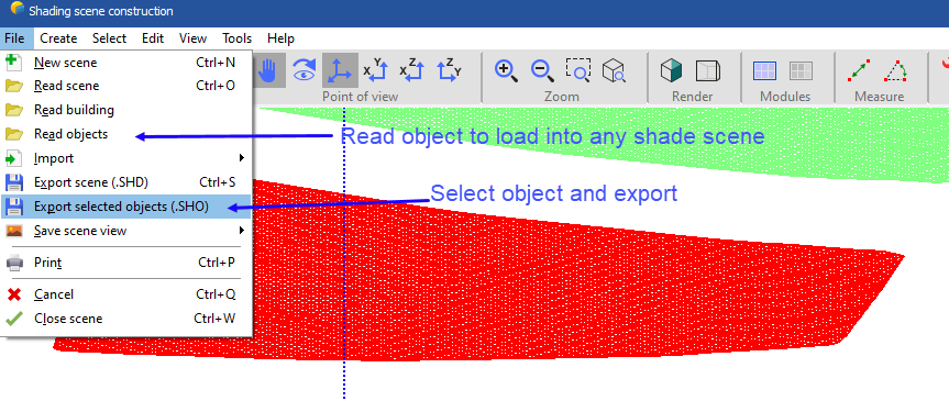
Once you have imported and set your PV panels, save the ground object as a shading object and delete it. You can always pull it back in. Do not reposition it prior to saving and deleting, and it will be imported exactly where it was last saved.
-
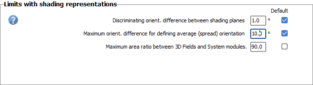
It looks related to the advanced settings not overriding the project settings. Adjusting this worked, but is limited to 90, whereas there is no limit in advanced settings.

-
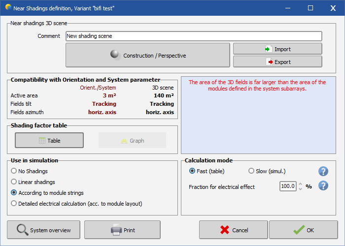
Getting an error even though the thresholds have been adjusted in system settings. 7.4.7. Bifacial system.
-
The PVsyst wind stow estimation feature is not available for Unlimited trackers N-S. Can this be added?
-
-
15 hours ago, hritik said:
When comparing different manufacturers for a particular site, I obtained the results which are varying. Are there any default parameters for PV loss due to irradiance levels and PV loss due to temperature in PVSYST? On what parameters do these factors depend? These come from the PAN file, resistance values/low-light performance, temperature coefficient
Is it possible to get gain due to loss from irradiance levels? Not sure what this means
What should be the ideal values for Module quality losses? There are no ideal values, depends on the one doing the simulation
-
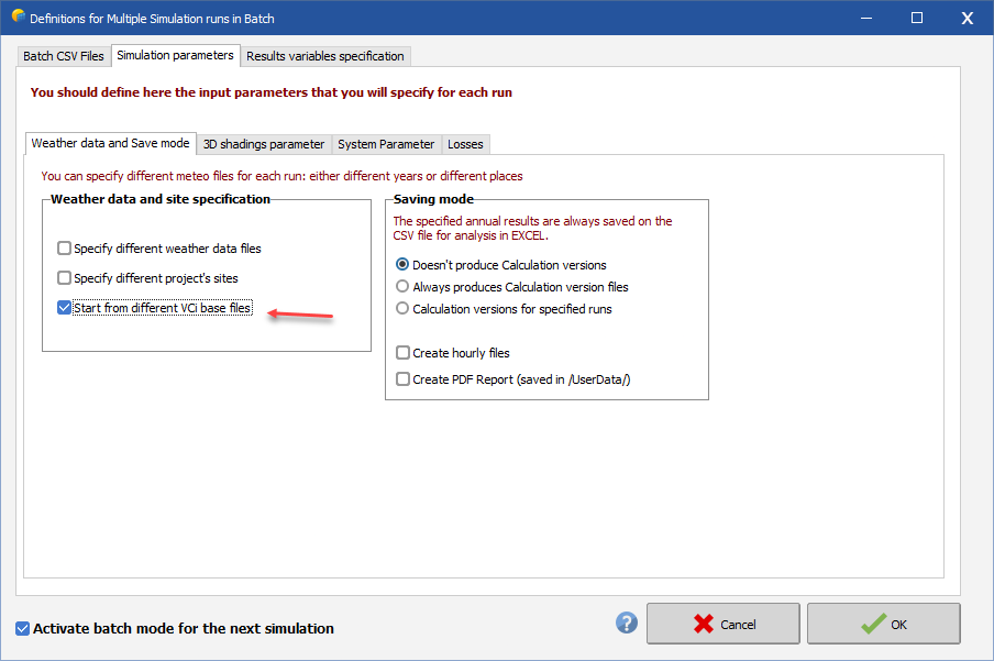
Create multiple variants with the different bifacial settings you wish to test (height from ground, albedo), check the box below. Spacing and tilt are a little different, those inputs for bifacial inputs are derived from other places (i.e., shade scene, orientation menu).
-
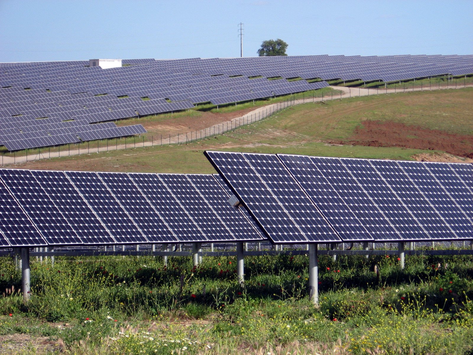
GlobInc. You might have reflections at low sun angles with that installation. For a fixed tilt system, these can be installed on a weather station free from shading and reflection.
-
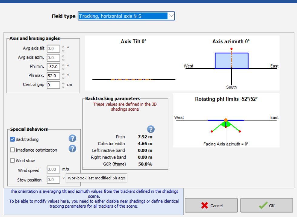
This can be seen in the orientation menu.
-
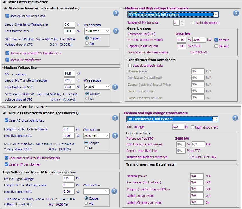
My guess is that the warning is with respect to the HV portion, which you dont have shown in the image. The OND file doesnt account for LV losses. LV losses are zero since the MV transformer is connected to the inverter. You will define a MV line loss however from the MV inverter(s) to the HV transformer(s). Since the OND file accounts for the MV transformer, maintain 0% in the no-load and full-load loss.
-
There is not unless you model each inverter separately in different variants.
-
You can model it in certain software. Here is one paper to reference. https://www.sciencedirect.com/science/article/pii/S2667113121000048
-
@Robin Vincent Is there a reason for a limit of 5 periods?
-
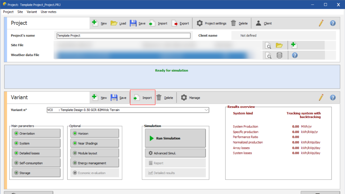
You can for example create a project called "Template Project" (Template Project.PRJ)which stores your template project variants (i.e., Template Project.VC0, etc.). Then when you want to use this template design in some other project, import the template variant "Template Project.VC0".
I want to simulate a fixed tilt and a HSAT (Horizontal single axis tracking ) both at a single simulation
in Simulations
Posted
You can take a weighted average of the PRs.