
Stéphane
-
Posts
76 -
Joined
-
Last visited
Everything posted by Stéphane
-

Orientation Mismatch Near Shading 3D Scene
Stéphane replied to MinkeK's topic in Shadings and tracking
Hello. Please send us your PVC file at support@pvsyst.com so that we can have a closer look and try to find the root cause. -
Real near shadings based in drone import
Stéphane replied to Carlos Arredondo's topic in Shadings and tracking
Dear Carlos, We don't have any specific procedures or instructions regarding existing plants. If PVC format is not available, DAE or 3DS can be used. Then on the import screen you can select the "material" that is used for your trackers and you can define the tracking parameters there. Also for the terrain, you can select its material and PVsyst will import it as a ground object. Here is the link of our help page for importing 3D file, where you will find more details: https://www.pvsyst.com/help/project-design/shadings/near-shadings-import/sketchup-and-other-cad-software.html#scene-details -
Dear Pattarporn, don't hesitate to email us your project at support@pvsyst.com so that we can replicate the issues and try to help you.
-
Near shading definition in 3D model (Spacing of 2-3 cm)
Stéphane replied to pongsakornnorcum's topic in Problems / Bugs
Dear Toni, don't hesitate to email us your project at support@pvsyst.com so that we can replicate the issue and try to help you. -
Dear ShivamPandey, Please email us your PVsyst LOG files (using menu <File> <Export logs>) at: support@pvsyst.com so we can analyze what happened and try to reproduce the issue you reported. Best regards.
-
Dear ShivamPandey, Please email us your PVsyst LOG files (using menu <File> <Export logs>) at: support@pvsyst.com so we can analyze what happened and try to reproduce the issue you reported. Best regards.
-
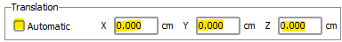
Hi. Thank you for the additional information. PVsyst reads the content of the PVC files and applies a translation if X/Y/Z are not 0. If you don't get the expected results, maybe there is an issue with the PVC files. Can you send us the 2 files by email at support@pvsyst.com? We will check further to identify the source of the issue.
-
Hi. On the import window of the PVC file, you need to uncheck "Automatic" and to set X, Y and Z to 0: This way each plot will be imported at its original location.

-
Thank you for pointing that out. This is a bug that will be fixed in an upcoming version of PVsyst. Sorry for the inconvenience.
-
The PVC file contains only coordinates of each corner of the trackers, so they will be placed in PVsyst according to those coordinates. Now how PVcase generates those coordinates based on the TFT option is a question I cannot answer. But my understanding is that you can adjust the "maximum allowed angles between section parts %" parameter in PVCase to make sure the scenario is realistic.
-
PVCase now has an option called "Terrain-following trackers" that splits trackers into smaller trackers according to gaps. Those trackers are therefore correctly positionned. This is the easiest option for now because the PVC format doesn't support the motor and joint gaps so this information is not included in the PVC file. However there is currently an initiative to define a new version of the PVC format. This version should support such gaps. However, currently there is no release date available for this new version.
-
Importing Shade Scene from PVcase File "too big"`
Stéphane replied to Isaiah O's topic in Shadings and tracking
There are mainly two reasons that can lead to this error message: The unit selected at the top of the screen is not correct There is a "lost" object really far from the origin of the scene Looking at the size after import at the top right of the screen, 212km and 175km seem way to high for a scene. The reason is likely the second one. Locate this "lost" object in the source software, delete it and export the file again. It should import properly into PVsyst. -
Hello. Hiding a ground image makes it white instead of transparent, that's why it is hiding the objects behind it. This is a bug that will be fixed in an upcoming version of PVsyst. Thank you for pointing it out and sorry for the inconvenience. Also, if you prefer using ground images from external softwares, you can delete the one that PVsyst downloads through the interactive map and use external ones only.
-
You are welcome, I am glad I could help. Changing the limits regarding the error messages never changes the results. Those messages are here to highlight the differences that might exist between the model, the system and the reality. It is difficult to evaluate the impact of those differences because they depend on the specifics of each project. The threshold of some messages have been changed between PVsyst V7 and V8 but the models have not changed.
-
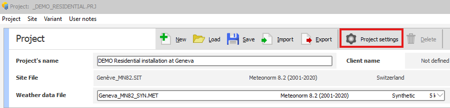
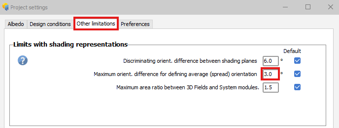
Hello, This error appears because the angle between your average orientation and at least one of your PV table is too high compared to the settings of your projects. To fix this error you need to increase this tolerance. From the main window of your project, click on "Project settings" at the top of the screen: Then you need to select the "Other limitations" tab and increase the value of the "Maximum orientation difference for defining average (spread) orientation" parameter: Once the value has been increased the error should disappear.
-
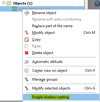
Hello, By default ground objects are not taken into account by PVsyst during the shadow calculation. On the 3D scene, in the objects tree on the right, you can right-click on the ground object and click on "Enable shadow casting": Then the shadows from the ground will be taken into account. I hope this helps.
-
Import file from rhino8 to pvsyst
Stéphane replied to Michalis Angeli's topic in Shadings and tracking
Hello Michalis. The issue is probably coming from the DAE file but it is difficult to answer without having access to it. You can send us the file you are trying to import by email to support@pvsyst.com and we will have a closer look. -
Import file from rhino8 to pvsyst
Stéphane replied to Michalis Angeli's topic in Shadings and tracking
Hello Michalis, At the top of the "PV objects" section you can choose between "Best azimuth", "Longest edge" and "East/West" to help PVsyst identify the correct azimuth. The "Apply 180° rotation" can be useful if for example your project is in the Southern Hemisphere. -
Import file from rhino8 to pvsyst
Stéphane replied to Michalis Angeli's topic in Shadings and tracking
Hello Michalis, In the "PV objects" section of the import window you need to check all materials that have been used in the source software for defining PV faces. This way PVsyst will transform those faces into PV panels and the shadings animation will work. I hope this helps. -
Error: Area error with 3D ground modeling
Stéphane replied to JoaoReis's topic in Shadings and tracking
Hello JoaoReis. You can send us your project files at support@pvsyst.com so that we can have a closer look and try to help you. You can export the project from the main window > File > Export projects. -
Hi. In sketchup can you try to export it as a *.3ds file instead of a *.dae file? Sometimes it fixes the issue. Otherwise send us your *.dwg file by email at support@pvsyst.com so that we can have a look.
-
Hello, Please send both files (the one that is working and the one that is not working) by email at support@pvsyst.com so that we can have a look. Thanks in advance.
-
Setup the Azimuth of PV System to 0° in Near Shading Simulation
Stéphane replied to Solaranger's topic in Simulations
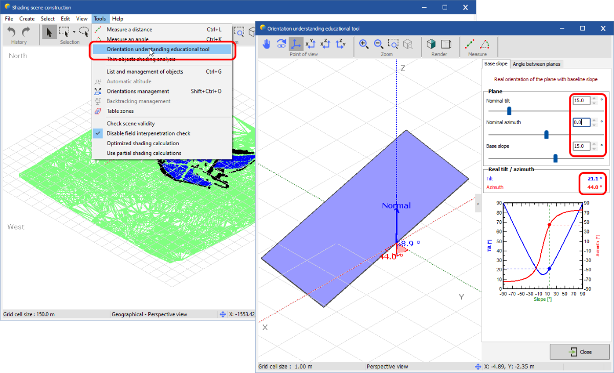
Your PV fields follow a ground slope. This introduces baseslope angles of each PV fields. That means that the real tilt/azimuth angles are not the same as the nominal ones (the 0° that you have defined). You can use the orientation educational tool to better understand this concept: So it is an expected behaviour that the real tilt/azimuth of the orientation is different from the nominal ones that you have defined. The nominal azimuth of the individual PV tables is still 0° as seen on your screenshot. However the azimuth of the orientation used in PVsyst is the real azimuth and not the nominal azimuth, because it is the real azimuth of the orientations that is used for the calculations. PVsyst displays the real azimuth in the report because it is the one used in the calculation. There is currently no way to change that behavior.
-
Hello, On your last screenshot you need to click on the "System" button. There you need to define 4 subarrays (one for each orientation) and each subarray should have the same number of modules and area than the corresponding orientation in the 3D scene. Then the error should go away. However, you should first determine if 4 orientations is the correct choice for your project. By looking at your first screenshot I see that your orientations are more or less similar. Are the different orientations only due to the slope of the ground or do you really have specific zones where all tables share the same orientation? If the different orientations are due to the slope of the ground then it would be better to have 1 orientation only (as long as all tables are on the same side of the hill) because with multiple orientations the tables belonging to the same orientation would not always be close to each other so they would not be connected to the same physical inverter and the simulation would be less realistic. To get 1 orientation only you need to increase the tolerance in your first screenshot and then click on the "Identify orientations" button. I hope this helps.
-
Hello. Increasing the tolerance works great if you want to end up with 1 orientation only. That would give much better results than planarize the base surface. It is usually the recommended approach if your panels are on an uneven slope and they are all on the same side of the hill.