

dtarin
-
Posts
779 -
Joined
-
Last visited
Posts posted by dtarin
-
-
Yes, by using the multi-mppt feature on the inverter, you can. If your inverter does not have it built in, you will need to add it yourself by modifying the OND file. Here is some discussion on the feature:
http://forum.pvsyst.com/viewtopic.php?f=3&t=2668&p=7107&hilit=multi+mppt#p7107
-
Hello,
Is this a typo in the attached image? The units on the graph axis shows celsius, but the Voc coeff is given in %/ degK.

-
1) I believe it is the number of rows in your design.
2) Yes, where shading losses are due to the preceding row.
-
Picture did not load. This has happened to me before, but I cannot recall how I fixed it. Did you try creating a new project?
-
It depends on the inverter. You can use multi-MPPT function and create three subarrays, one for each orientation.
-
Perhaps something like this? https://www.nde-ed.org/GeneralResources/Uncertainty/Combined.htm
-
Hello,
I have two different ground images imported into a shade scene. Is it possible to change which one is viewed on top?
Thank you.
-
Hello,
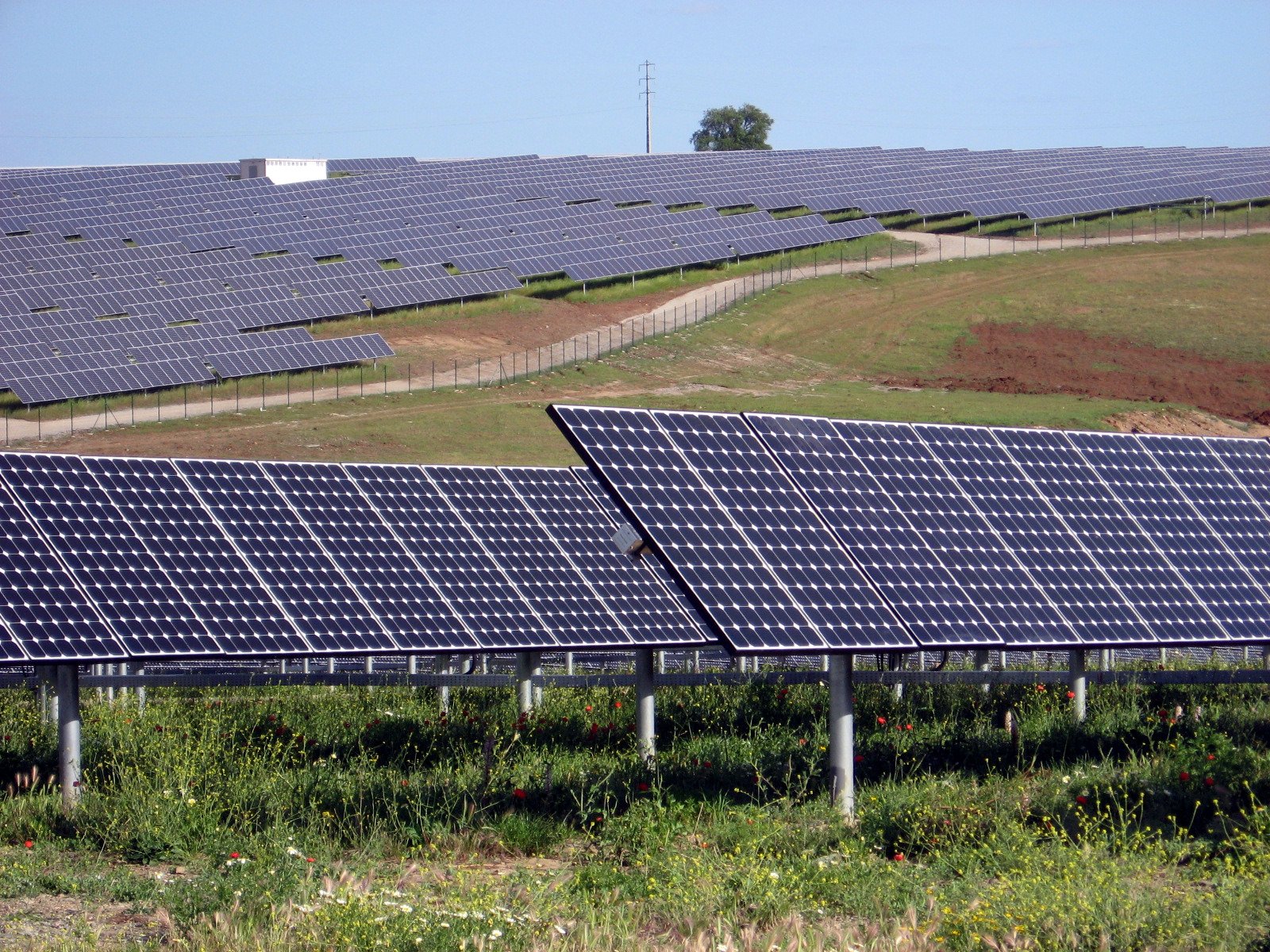
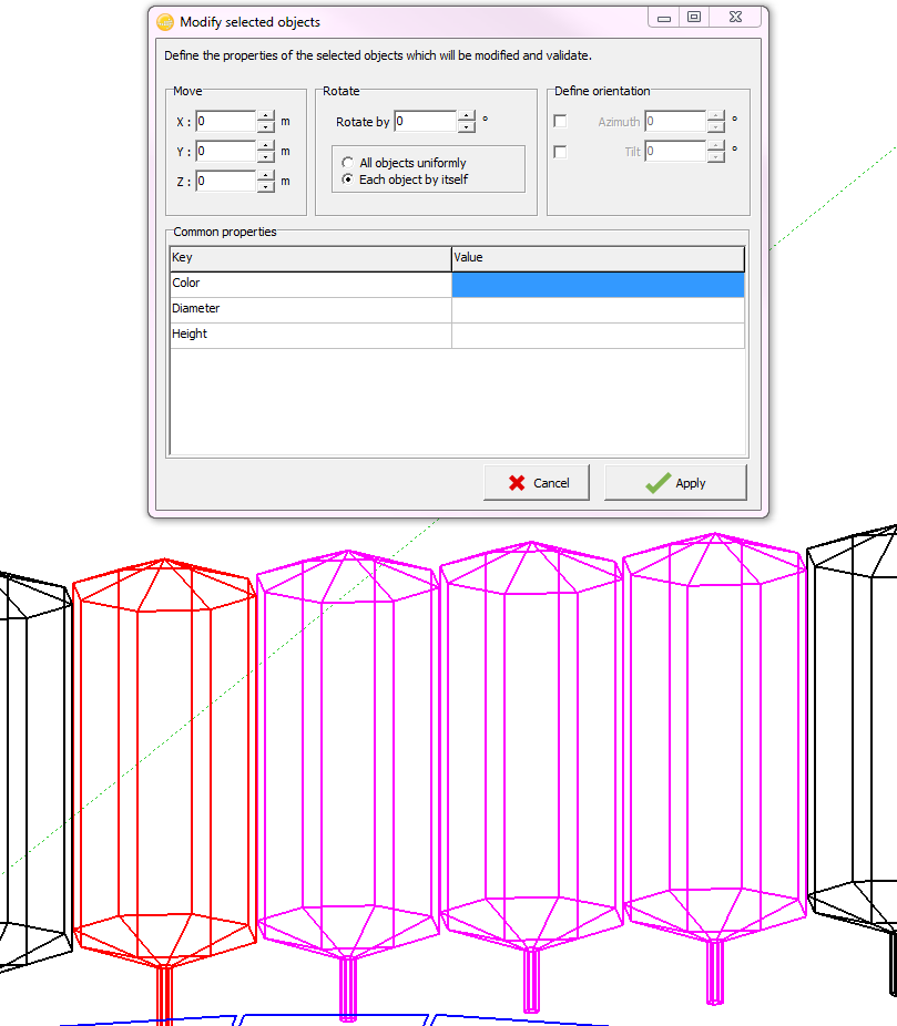
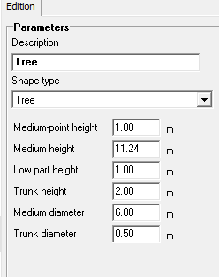
Often we need to make adjustments to tree heights once survey data has come back. After having performed an initial topo survey, created a ground object based off this data, and dropped trees and panels onto the ground object, it can become tedious and time consuming to then go through and update every tree or other objects individually.
It would be useful and efficient if all of the parameters for a tree (or some other object like parallelepiped) were available in the modify objects menu (when selecting multiple objects). These fields already exist individually, and perhaps just need to be linked to this menu. That way, when certain objects need to be adjusted in in some way but remain in the same location or keep other parameters fixed, one or more fields can be modified in the parameter(s) needed and have the others kept constant. Currently, it looks as though PVsyst accepts the new height (for example when modifying a tree) and distributes the change across all of the parameters.
-
Without knowing the model and seeing the data it could be temperature derating if it's like a PE 1500V. If greater than 25C your nameplate changes.
-
I have not. What version?
-
What is the inverter?
-
If you are trying to import a PAN file, place it in your directory ...\PVsyst6xx_Data\ComposPV\PVmodules, close PVsyst, and reopen (if you have it open). It will be listed in your module list now.
-
I dont quite understand what the difference is with using cells versus modules in series, but if you use modules (ie 18 modules in series, 10 in parallel), the calculation is much different.
-
Thanks Andre.
It is not clear to me a specific tool is necessary. All of the specific tools for the different meteo sources are already in place. I think all that is missing is the automation end from PVsyst and how to handle the inputs. I think on the PVsyst end, perhaps the only modifications are what to name the file, and which files to select. The data source is the same for all files imported, and the time zone can be retrieved from the web service for each file. If a user directs the program to a directory containing N TMY3 files, and selects TMY3 as the data source type, perhaps PVsyst can use the file name as the site name and weather file name, and simply step through the process for each file.
-
Hello,
Is it possible to execute a batch run using different monthly weather profiles, instead of a single value?
-
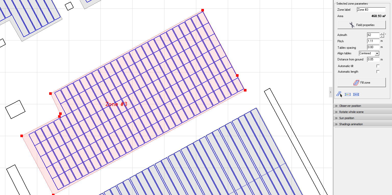
Hello,
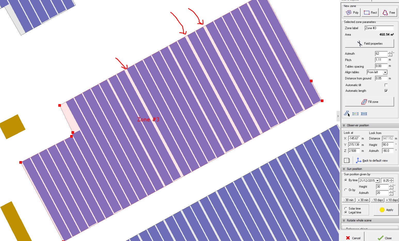
I am using version 6.6.3 and I have noticed that when I set a pitch and fill a zone, not all rows are set with the pitch assigned. Please see attached image. Can you provide any assistance or insight into what is occurring?
Edit: It seems this occurs when automatic length is used. We can see in the 'zone filling' picture with automatic length selected that the rows still do not end up equal length. The second image 'zone filling 2' has this option unchecked, and the zone fill is as it should be, with rows equal length and all with the appropriate spacing.
-
Every time I import a ground image and close/reopen the project, the ground image resizes itself, and I need to re-enter the scaling number.
-
For the calculation of the backtracking angle, PVsyst has to use the pitch and wdth of 2 adjacent trackers.
This is only possible with trackers of a same tracker object (array of trackers). When you have several arrays of trackers, PVsyst will choose the more "narrow" as reference.
I read this as stating that PVsyst requires two trackers to be at the same orientation (no misalign or azimuth changes). If I have two trackers of the same orientation, and another two that are misaligned which are adjacent to the first two, is this acceptable and able to be properly captured? See image for reference.
Thank you,
-
I don't understand what you are doing.
By the way, you cannot use the backtracking strategy with a misalignment of the trackers.
See the FAQ How is defined the Tracking Axis azimuth ?
Andre,
Backtracking with misalignment isn't forbidden in PVsyst. Are you saying that if it is selected, the results are not accurate?
-
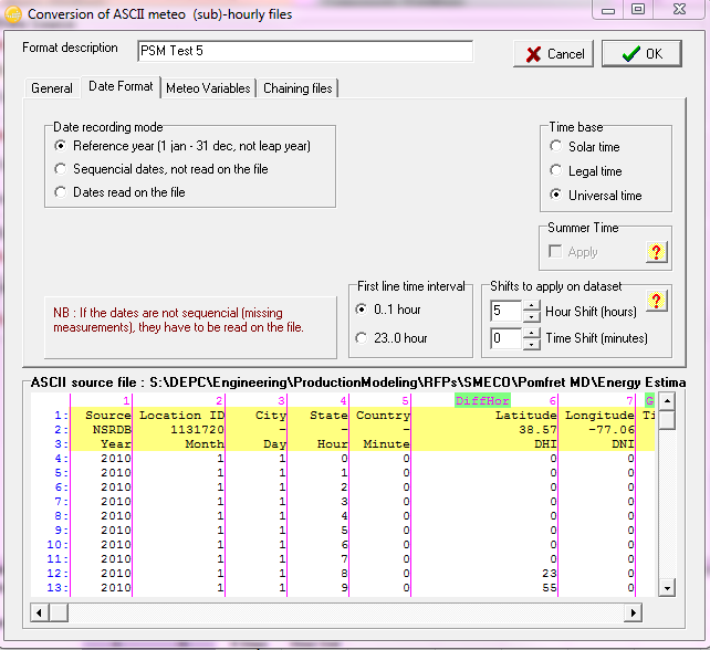
For the time shift issue, see attached image. Apply a time shift in hours, run it and check, and adjust as needed until you are able to timeshift with 30 minutes or less. It is a trial and error process.
-
Change your setting in hidden parameters. But it looks like that you need to recalculate, as that is very close, and shouldnt give the error.
-
I think he meant that we would like to misalign the modules to the eastern direction. Entering a positive value for misalign points them to the west. Entering a negative value for misalign points them east, but this it not allowed. I also would like to misalign to the eastern direction, but do not know how (or if it is possible) to do so.
-
I have asked to several different inverter manufacturers and all of them have answered that there will be an active power reduction due to a PF less than 1, only in case of overload
This is exactly what I said in my first answer to this post.
The active energy production will not be affected, until the Pnom limit (in kVA) will be reached. The power factor acts as a diminution of the nominal output power (Pnom) expressed in terms of active energy [kW].
In your example: Pnom (apparent) = 60 kVA => with 85% PF Pnom (active) = 51 [kW] will be applied for limiting E_Grid when running the symulation.
PVsyst works in this way of course.
Andre,
Will PVsyst work in the same way with inverters which have a temperature de-rate curve established in the OND file, such that the entire de-rate curve is multiplied by PF?
-
Hello,
It would be extremely useful if it were possible to import multiple meteo files at once and automate the creation of multiple MET and SIT files.


Definitions
in Shadings and tracking
Posted
Pitch: Post to post distance
Coll. band width: width of the modules regardless of angle, i.e. if two in portrait, coll. band width is length of module * 2 + spacing between modules
Inactive band: distance the underlying structure extends past the module area. Often times this is zero.
GAOR: collector width/pitch