

dtarin
-
Posts
777 -
Joined
-
Last visited
Posts posted by dtarin
-
-
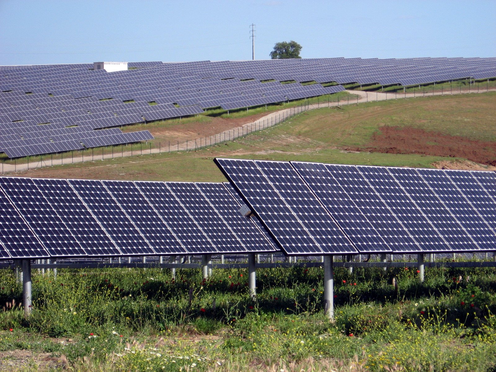
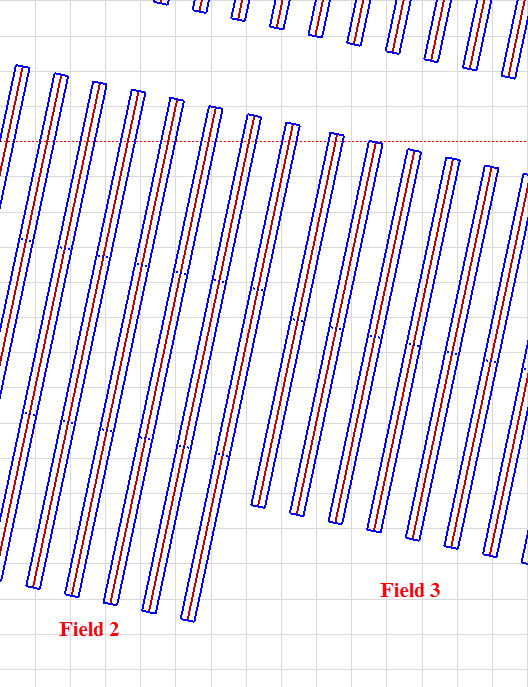
Hello,
I have two tracker arrays shown in attached image one, where the length of rows is different for the two blocks. If they are set to zero azimuth and placed adjacent to one another (with the spacing shown in image 1), there are no errors. If I change the azimuth to say 12 degrees (image 1), I get the error message shown in image two. The two arrays are separated by >5m. Is there a bug which arises when the azimuth is changed? The arrays need to be separated by more than 11.12 meters for the error message to go away. PVsyst version 6.63.
Thanks.

-
What PVsyst version are you using? I am using 6.63, and the -30 time shift saved for me. I updated the .MEF file, saved, ran it, closed PVsyst, and reopened, and it was still there. When I run it again, a -30 time shift shows up.
-
Not to my knowledge. Trackers are not as flexible as fixed tilt systems in terms of modeling in a shade scene, and there are limitations to them (ie misalign and ground terrain situations).
-
#1) In a N-S tracker system, pitch is the E-W distance from post to post for the tracker. This can be verified in the shade scene once constructed.
#2) The option is called Tilted Axis to select N-S tracker.
-
Hello,
I am trying to use the parameter optimization feature with a shade scene to simulate different azimuths, but the feature is not working. It works with unlimited sheds, but not when I have a shade scene. There is only one orientation in the shade scene. PVsyst version is 6.66. Also occurs with 6.63. Does anyone else have this problem?
-
If you are talking about DC ohmic losses, just enter the percentage you want to use. Click the cursor into the wire resistance field above after updating the percentage, and then click back below into the percentage field. The mOhm should update when you first click into it after updating the percentage.
-
Hi emilie_g,
Once your zone is created with tables, you can uncheck the zone icon at the top menu bar, and then simply shift+click the modules you want to remove from the zone and press delete.
-
Hello,
When running a batch simulation in a project, I have specified different variants to run for several simulation lines. When I look at batch results, the values for all simulation runs (regardless of the variants specified) show only the results from the variant that the batch simulation is being initiated from. So if I want to run a batch simulation for variants A, B, C and execute the run in variant A, I only get data from A.
Is it possible to do what I am trying to do? I had thought that I could specify different variants under Simul field and the batch simulation would run that simulation variant within the project.
Ident;Meteo data;Create hourly;Soiling;Simul;
SIM_1;A.MET;AA.csv;1;A;
SIM_2;A.MET;AB.csv;1;B;
SIM_3;A.MET;AC.csv;1;C;
Thanks,
-
Hello,
Is there a variable for outputting soiling loss in the 8760 file?
Thanks.
-
Hello,
I am aware of what the differences are between GlobEff and GlobInc as stated in the PVsyst documentation. What I would like to know is if one of these is better suited for evaluating plant performance depending on the irradiance sensor used, such as a pyranometer or Si reference cell? And perhaps not just GlobEff, but the other corrected incident energy parameters as well. What would be a physical or practical application of these parameters?
Thanks.
-
I dont have them in my library, but RECOM has a bifacial module.
-
Make sure you click on "Apply" after you defined the X1 and X2 points or else nothing will happen.
Thanks Sylvain.
Has anyone experience problems with the ground object scaling being removed after reopening the project? I have experienced this with different projects and it is time consuming having to re-apply scaling with correct referenced dimensions. I am wondering how could I avoid this? Thanks.
Update to 6.64.
http://forum.pvsyst.com/viewtopic.php?f=4&t=3036&p=7765&hilit=ground+image#p7765
-
Is it possible to have trees or other objects be automatically placed onto ground terrain?
-
In hidden paramters set default module spacing to 0 and and reimport, see if that helps.
-
Set the small array to 0.3, the larger to 0.7.
-
Yes, this is annoying. It has to do I think with the default settings for module spacing. Best case is to set it to zero in hidden parameters, so that when you import a project or shade scene, it doesnt rearrange the table by changing the table size. If the scene was set with .01m, and your default is .02, there wont be enough room in the table, so itll switch orientations and make number of modules accomodate the table. It would be nice if PVsyst automatically adjusted, or had an option where hidden parameter settings dont override the shade scene like that.
-
Is the overall system size 41.3kW DC, 33kW AC? If so, use fractional inputs option in both arrays.
-
Where is your TMY data from? Maybe you can:
1) change the coordinates in the tmy data file to match the site you want to use. The import into PVsyst as usual. When you load your project, you will have your desired site selected, and then you can switch to your MET file with the desired tmy data
2) create the site, then use the ASCII input method to import your tmy data, selecting the site you want to be associated to it
3) change the project settings and increase the distance allowed for met files to be used from the site
-
I have currently the chance to export SRTM terrain data from WindPro in the following formats:
btw: there's no need for windPro, you can simply download SRTM-Data in GeoTiff from here
Can you elaborate on how to use GeoTiff data with PVsyst? What program do you use to extract the terrain data?
Thanks.
-
Hello,
Since PVsyst cannot model trackers on uneven, undulating terrain, does anyone have any information or guidance on how one can approximate performance of single axis trackers with backtracking for these cases? Has anyone done any analysis with data from a site with these terrain conditions, to come up with some sort of de-rate factor?
Thanks.
-
Do the 5 inverters each have (1) 20 string and (3) 21 strings? If so, you will create two sub arrays, each with 5 inverters and multi mppt checked. Subarray A has 5x20, subarray B has 15x21
-
Module quality (negative indicates over performance)
-
Pitch: Post to post distance
Coll. band width: width of the modules regardless of angle, i.e. if two in portrait, coll. band width is length of module * 2 + spacing between modules
Inactive band: distance the underlying structure extends past the module area. Often times this is zero.
GAOR: collector width/pitch
-
Yes, by using the multi-mppt feature on the inverter, you can. If your inverter does not have it built in, you will need to add it yourself by modifying the OND file. Here is some discussion on the feature:
http://forum.pvsyst.com/viewtopic.php?f=3&t=2668&p=7107&hilit=multi+mppt#p7107


Multiple modules in 6.67 reports
in Suggestions
Posted
Hello,
It would be helpful if module specific inputs were listed for each module in the PDF report, such as IAM profile, LID, etc. For LID it looks like it gives an average both in the waterfall and in the simulation parameters section on page 1 or 2, which makes it impossible to confirm which test data has been used for each module.
Thank you.