


tecnun
-
Posts
134 -
Joined
-
Last visited
Everything posted by tecnun
-
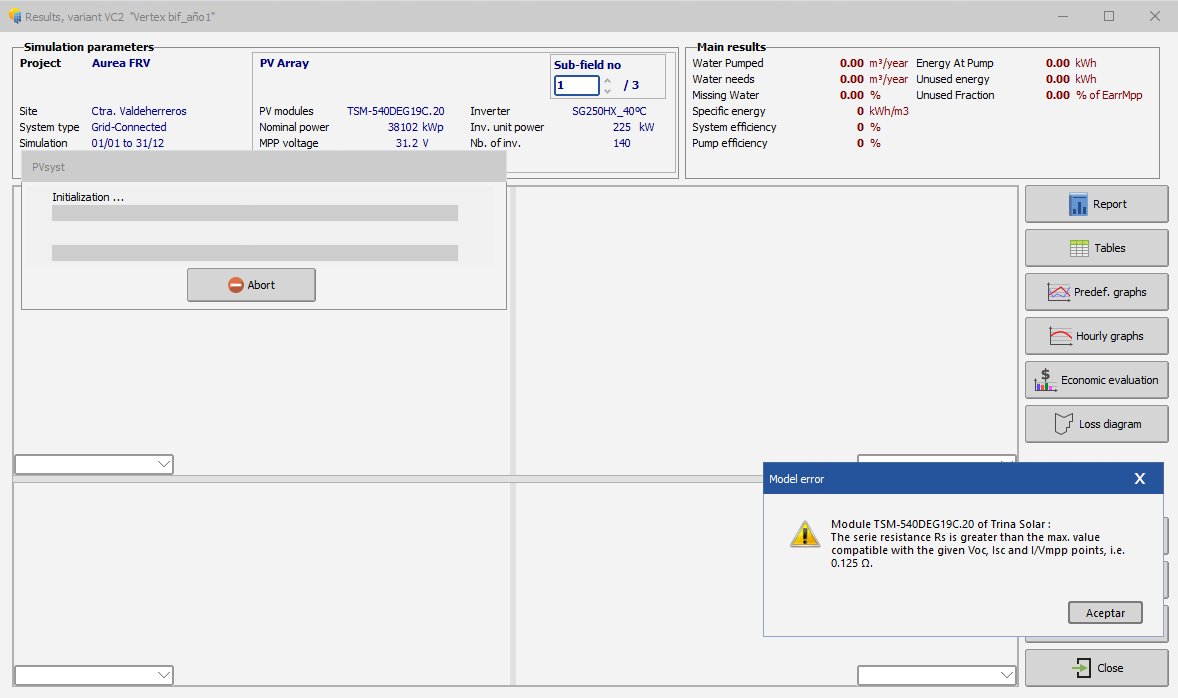
Hello André and Team, Simulating a PV Plant with our Client .pan file (defined parameters by 3rd Party tests) we realized there was a problem with Rs definition. I´m attaching warning of too high Rs definition, so we made a simple test: We created a new module definition with half Rs value (0,059 instead 0,118) and we surprised that simulation yield was similar even a little bit worse. As we know if Rs decreases, gamma increases, I-V curve "flatten" and module power decreases, at least in our understanding (please correct me if I am wrong). Is it PVsyst model correct?? It is charted in your tool (you can see it also at the images we attach) that changes are minor indeed, yes in this case a little bit better shape factor with Rs = 0,059 (half Rs), but a minor difference (but gamma now is higher!) Is it something wrong with simulation and/or graphical tool? What am i missing? We hope this could be analyzed, best regards

-
Hello Team, In electrical ohmic losses dialog box, we set the inputs of LV/MV losses in a certain %. But it is important to know which base we are using. For example, in DCLV electrical losses it is common to use peak power, and in ACLV inverter nominal power (at design temperature). ACMV is a little bit tricky and some ppl use certain base and others another base. But we are seeing that the base is the same for all 3 configurations, I am attaching an example. In this example you it is proved that DCLV basement is STC so peak power (ok) but for AC, we are seeing a strange basement (it seems like it is STC DC corrected by european inverter efficiency). In this example it is the same for both LV and MV = 118.124 kW, whereas the peak power STC is 119.750 kWp Which base this is standing for? Is it what we suspect (STC x european efficiency)? Thanks in advance, BR Tecnun
-
Hello Team, We are wondering if the GlobBak parameter simulated and exported to csv reflects exactly the effective irradiance on rear side of a bifacial module that it is receiving, or it must be multiplied by the bifaciality factor. e.g: GlobBak = 200 W/m2 x 0,7 = 140 W/m2 This question comes from the calculation that SANDIA method does of Voc every hour of the year. They say we must multiply it but we are not sure, in fact we believe the bifaciality affects only on the yield conversion but not in irradiances, so Voc is affected by 200 W/m2 in the example, and so cell temperature variations, to build a Voc = f (Irrandiance, cell temp) basically. Thanks, PD: By the way...which method PVsyst employes to calculate hourly Voc or Vmppt?
-
Hello again, i ve just encountered the solution by browsing the "help". As its name says it can help you :D Has anyone gone through this issue, I can guide you guys quickly to resolve it, it is really great explained in "Help" options, thanx PVsyst Team for your improvements BR José
-
Hello, good day I have a problem with a common configuration: 15 strings per inverter with a 12 MPPT (24 input) string inverter (Sungrow eg). It shows up a message like this : <<9278 inputs with 1 string and 2966 inputs with 2 strings, consider disabling "use Multi-MPPT feature" for ensuring power sharing on each input>> 2 involved problems: 1- It takes 90 minutes to simulate whilst without this Multi-MPPT activation it takes less than 30 seconds 2- It applies more than 9% of overload losses Is there something wrong? These configurations are usual, as it results quite "lucky" that you can fill out all the 12 MPPT with 2 inputs per MPPT (24 inputs) Please we need some feeback or related question if you guys need more details BR Jose (Madrid,Spain)
-
Hello Team, Is it possible to generate and calculate a 3D shading losses scenario with trackers 1P (eg created by Helios3D), taking into account that due to topography, these trackers have uncountable different orientations? Do we still have to "flat" them or now it is possible to calculate every single orientation/slope? In all cases bifaciality must be considered. Thank you in advance, best regards Jose
-
Hello Team, Is it now possible to calculate shadings with a 3D shading scene of trackers (bifacial module) in the case these trackers have different orientations due to the orography of the site? And if not yet, 2 questions: is it intended to do it in the short run? And the other question: if there is not bifacial module is now this possible? if it is: How you can simulate and it? Is it easy? Thanks in advance Best Regards
-
Hello, I have encountered a problem when it comes to design long string sizes in warm locations. In project settings you can set the temperature but it cannot be higher than 30ºC so in system you are obliged to limite the string size (as it turns "red" if, for instance, Voc > 1500 V). I suggest to widen the temperature range to 40-45ºC (now this ranges from -40 to +30) bcs more and more utility installations are requiring for ex. 31-32 modules per string in very warm locations (like Colombia) Looking forward to it in next versions, my best regards Jose
-
Hello, I am simulating fields according to module string partitions (eg 90% electrical effect), disposing modules (72 cells, NO half cell config) in vertical or horizontal, and the results are almost exactly the same, when you would expect better results for 2H vs 1V as the bypass diodes can take action (even in 2H are worse results in terms of IAM, transposition gain and shadow losses) In both there is 0% electrical losses. Am i wrong or there is no real distinction. Now i am wondering if without strings partition as 1 block the results are being always (almost) the same. BR, Jose
-
Good day, I ve spotted a bug in the mismatch losses accountability. In 7.0.2 in inputs, the second decimal is ignored. For example, if you type 0,55% it reflects 0,5% BR Jose
-
Thanks Dtarin, I m getting now the discriminating factor, eg if you have only 2 tables and they differ each other 1° if you choose 2° the system will consider them equal, but if you set it to 0,5° there will be 2 different orientations. Concerning the other condition i stll have doubts. So if, going to the hereabove example, you add a third table wihich differs the other 2 more than 10° and you choose limitation of 10° what happen? BR Tecnun
-
Hello, When you import 3D scene from Helios3D or any other mean, is it possible to define every table with the position (horizontal or vertical) and anchoring of modules, without having to do it table by table? Sometimes, for instance when modules are landscape, it is more accurate to place them like that, so partial shadings are less harmful as bypass diodes work. Looking forward your feedback, BR
-
Hello good day, I would like to know exactly the difference between these shading conditions in Project Settings: - Discriminating orient difference between shading planes - Maximum orient difference for defining average spread orientation What do they stand for? For instance, I am working with shading scenes imported from T3 in a non-flat terrain (real topo scene). By default the system brings me to define +8 orientations. But I would like to define 3-4 main orientations and distribute them in 3-4 subarrays (unless terrain is very flat, which i prefer to define 1 average orientation-slope) Dont know if i have explained... BR Jose M (tecnun)
-
Hello PVsyst friends and PV family, We are experiencing different yields after a simulation, whether you extract the pdf report or you imported from csv hourly values. Why this happen and which of both methods is more reliable? Maybe in next V7 this issue is fixed? It's crucial for my Company to be absolutely precise, as small differences dictate whether the Project is or is not bankable (given that our inputs are too ?) BR Tecnun
-
Hello Team, I ve spotted a couple of bugs concerning Horizon label: 1) When you open it (once you have created before eg) and click diffuse factor label, when you return, your simulations disappear 2) More about diffuse factor label: First time you go in a project you can choose albedo, but later on you cannot access anymore Talking about albedo, it seems that 3 albedos are present: - Project albedo - Rear albedo (bifacial) - Horizon albedo I can understand that rear and horizon albedo could be different, but there exist also project albedo (in project settings)... what does stand for?? Or when you fix it (eg 20%) it reflects in both rear and horizon... Thanks a lot Best R. Jose
-
Thanks André i didnt spot this useful new tool, Fdez de Arevalo, are you sure you want to set -18ºC? Dont you think is too low? Take into account that that temperature is set in Standard Conditions and i am supposing that in midday and 1000 w/m2 the CELL (not ambient) temperature must rise Of course i dont know how cold your site is haha!! just for you to check it out... BR Jose
-
Thanks a lot André BR
-
Thank you André BR
-
Hello Team, I don´t know really what this parameter stands for: "voltage drop across series diode", in the array losses configuration. What´s its physical meaning, was it neglicted before? or now just it is isolated for individual study. I m appying it with default value of 0,7 V but i would like to understand it better. Thanks in advance, Best R. Jose
-
Was it useful? BR Jose M
-
It was solved in the past 6.7.5. Thanks a lot!!
-
Hello Team, I m wondering whether the new Meteonorm 7.2 Climate data also take into account terrain topography or we have to create an Horizon profile to set horizon shadings. Looking fwd a feedback, Best Regards Tecnun
-
Hello again, I ve just changed minimum temperature to consider at Open Circuit for max tolerable voltage at inverter: From -10ºC to 11,5ºC (which it is more realistic at 1000 W/m2 for our normal sites) but it keeps calculating at -10ºC, yes you can change it in hidden parameters but no effects in simulation. Am i doing anything wrong? BR Tecnun
-
André, i m attaching smth could be interesting for you guys. Please everyone consider it confidential as it took me time to make it. In my opinion sometimes IEC and other Norms should be updated (or refined). As you can see (sorry that it is in spanish if you want i can translate this excel), i m supposing 0ºC (ambient temperature) and maximum radiation (close to 1000 W/m2) which in Mid-Chile could be rare as it happens at solar midday. And the worse case: The Plant stops and resumes at midday (in these events we consider Open Circuit not mppt). At any time Voltage exceeds 1000 V. Taking into account -10ºC of cells in PVsyst there is noway we can select a 1000 V inverter. Would it be complex in PVsyst to develop SKOPLAKI formules? Good to be able to change Temperature (i didnt know it was possible), but as you can see in my excel, wind speed, height of anemometer at measures, rugosity of terrain, voltage drop upstream of the inverter are also present. Best Regards Tecnun Justificación Tensiones máximas SKOPLAKI_2.rar
-
Dear Team, I ve always had to "cheat" module and inverter maximum voltage due to open circuit string exceeding in unreal conditions, in order to avoid stopping simulation. In my opinion Voc (-10ºC) is an unreal restriction, as cell temperature is a lot higher in reference to ambient temperature. It implied a Polar temperature!. As we know voltage drops it temperature raise. Only this gap is small when there is no much radiation (and therefore voltage drops for other reasons) Would it be possible to correct this bug? Best Regards Tecnun
.png.e07de276b6d9342186c9c4f9d19160ed.png)
.png.882250bac5eb7dbe97f56bf2bcfa5e66.png)
.png.039d362f2efdc9325c434a746634b554.png)
.png.3d74e7896881b7b58951136ad9b62670.png)
.png.ca6a58a8510d7e29d32d08a1c5ac14b8.png)