tecnun
-
Posts
134 -
Joined
-
Last visited
Everything posted by tecnun
-
Hello Bruno, and thanks for you analysis, In my opinion, we are overprotecting our system at the expense of a superconservative design. Just a few thoughts: - We are assuming that in the event of a really cold cold day, assuming that the cells have not heated yet, during a daytime and under an irradiation over 500 W/m2 an event of electrical shutdown and reconnection (only at those events there exist open circuit conditions) - We are assuming that at abovementioned event, there exist no quality, mismatch, soiling, DC ohmic etc losses - We are assuming that the inverter does not protect itself from avobe 1500 V events. We have being chatting about this issue with the main inverter suppliers - We are also assuming that this "fatal" event is befalling at the very beginning of the PV Plant COD. We must take into account in my opinion LID and natural degradation PVsyst is, so far, accounting in Design Conditions (Project Settings) CELL temperature at this worst case event. Our proposal is to limit string sizes, but taking into account the "real" worst case. Is it too difficult to program this algorithm? Changing module parameters in my opinion is too risky and complicated to bring to a measure. Looking forward to your feedback BR Tecnun
-
Thank you very much Lazare
-
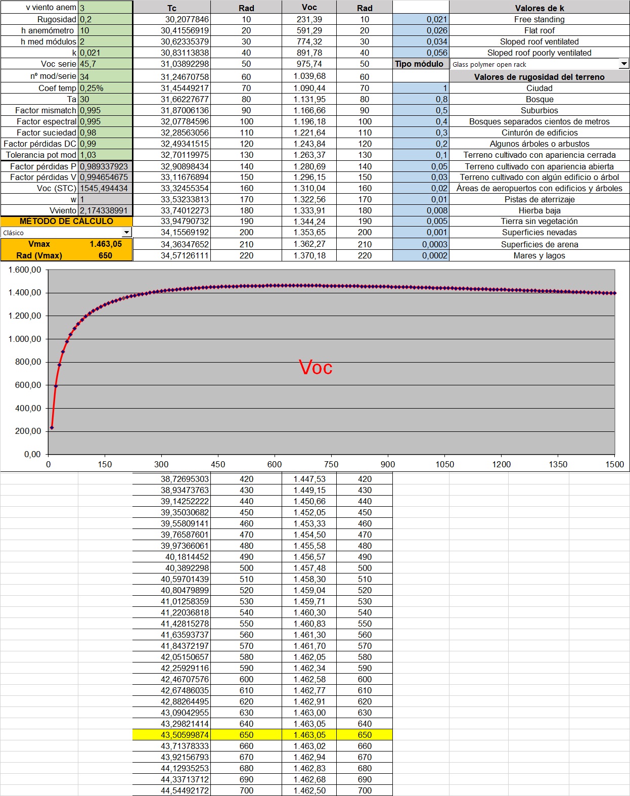
Thanks Lazare, Just as an example (SANDIA): It´s common to find the Voc peak in the range of 600-1000 W/m2 of POA, so in cold days the lowest daytime temperature does NOT determine the highest Voc. Let´s bring this scenario to a warm equatorial site like Colombia: There exists the real possibility of designing with 34 modules per string, and the maximum Voc (1.464 V < 1.500) happens at 650 W/m2 and a cell temperature of 43ºC. If we are limited to cell temperature of 30ºC, this would lead us to set the ambient temperature in this simulation to 17ºC, and the peak Voc now would rise to 1.512 V, so we would have to limit to 33 units per string. This is only an example. The main problem is that in PVsyst you fix the cell temperature, but it must be a combination of temperature. wind and radiation, so my suggestion is to build internally what i have made in an excel, taking into account METEO yearly data not just a cell temperature, dont know if i ve explained... BR Tecnun

-
Thank you Michele, it's now quite clear BR Tecnun
-
Tracking mode electrical losses. Bactracking algorithm
tecnun replied to tecnun's topic in Simulations
Perfect, thanks Dtarin for your huge knowledge of this software, I ended up thinking you worked for PVsyst Team because of that knowledge and generous help haha. Yes, it may be a challenge to optimize other more sofisticated tracking algorithms like the one you propose, hope this could be eventually implemented Kind regards Jose -
Tracking mode electrical losses. Bactracking algorithm
tecnun replied to tecnun's topic in Simulations
Thank you and sorry for so many post replies. I understand now (hopefully!!), factors like FshdAlb are then divided by ALBEDO irradiation ONLY thats why they are in my example so high (1-factor so low) but they add few ABSOLUTE (global) shadings, is that correct? The question about why there is no beam losses is bcs we are analysing tracking modes without objects like trees or buildings etc, so they reflect the inner algorythm that the movement of the tracker and its backtracking is forced to avoid ANY beam loss, correct also? If we were simulating fixed structures there should exist beam losses that would be aggregated to the global loss as if there were linear, and they would add another extra loss called "electrical losses" depending on 1P/1H configuration and depending on the number and effect of bypass diodes (or if it is half cell...), right? These things are being set in equation i supposed. What there is not being computed i guess is to consider another backtracking algorythm depending on these last paragraph factors (1P/1H, half cell, diodes...) right? is it being in your software development for futures versions? Again so thankful for your help BR -
Tracking mode electrical losses. Bactracking algorithm
tecnun replied to tecnun's topic in Simulations
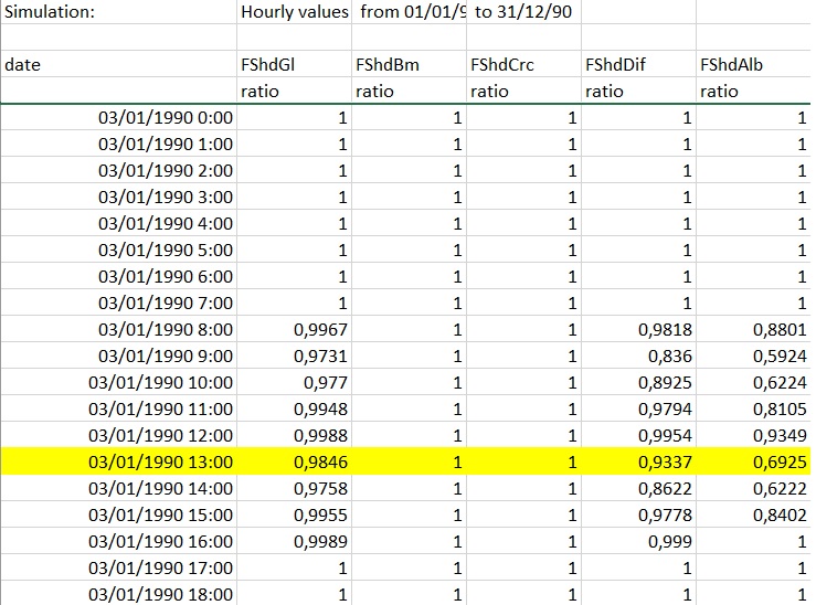
Thanks Dtarin, Sorry but I still have not understood these exported figures: What do they stand for? I ve highlighted one specific hour where FShdGl, FShdDif and FShAlb are not zero, FShdGl = Global ?? Global = Direct + Diffuse, there is no direct shading so it should be equal to FShdDif as far as I know... Anyway i still dont understand why there is no direct shadings, they should be the most important ones, shouldnt they?? Please need some help :idea:
-
Tracking mode electrical losses. Bactracking algorithm
tecnun replied to tecnun's topic in Simulations
Edit: I think the attenuation factor is something separate from the diffuse shading factor, which is "..independent of the sun's position, and therefore constant over the year...". From how the manual reads, the attenuation factor is something the software calculates when there are shading objects in the shade scene. So if you have trees or buildings (or basically a non-zero beam loss), you will get a non-zero attenuation factor. If you do not have objects, this factor remains zero. "The diffuse attenuation factor should be calculated, by integrating simultaneously the shading factor due to horizon, the near shadings factor according to the table, and the IAM attenuation factors over the visible part of the sky hemisphere. " - We dont know the integrals being performed, but perhaps if near shading (beam) is zero, the result is zero. In the case of backtracking mode there is no attenuation factor, all the shadings come from diffuse+albedo, this is absolutely clear thanks for last response. But, looking deeper to the hourly shading factors, we observe that, apart from diffuse and albedo, there exists global factors below 1, which to my understanding they should be equal to diffuse (global = direct + diffuse). Am I right? Could it be a bug? BR
-
Tracking mode electrical losses. Bactracking algorithm
tecnun replied to tecnun's topic in Simulations
Edit: I think the attenuation factor is something separate from the diffuse shading factor, which is "..independent of the sun's position, and therefore constant over the year...". From how the manual reads, the attenuation factor is something the software calculates when there are shading objects in the shade scene. So if you have trees or buildings (or basically a non-zero beam loss), you will get a non-zero attenuation factor. If you do not have objects, this factor remains zero. "The diffuse attenuation factor should be calculated, by integrating simultaneously the shading factor due to horizon, the near shadings factor according to the table, and the IAM attenuation factors over the visible part of the sky hemisphere. " - We dont know the integrals being performed, but perhaps if near shading (beam) is zero, the result is zero. In the case of backtracking mode there is no attenuation factor, all the shadings come from diffuse+albedo, this is absolutely clear thanks for last response. But, looking deeper to the hourly shading factors, we observe that, apart from diffuse and albedo, there exists global factors below 1, which to my understanding they should be equal to diffuse (global = direct + diffuse). Am I right? Could it be a bug? BR -
Tracking mode electrical losses. Bactracking algorithm
tecnun replied to tecnun's topic in Simulations
Ok that's really clear. I guess this plot of angles in fixed structures considers the same pitch, bcs if we decrease it the albedo shading would remain... Thanxs again Dtarin -
Tracking mode electrical losses. Bactracking algorithm
tecnun replied to tecnun's topic in Simulations
Sorry, what is the role of ALBEDO in this case? I forgot to mention before... BR -
Tracking mode electrical losses. Bactracking algorithm
tecnun replied to tecnun's topic in Simulations
Thank you Dtarin, Just for double checking: The shading losses are composed by these items: 1) NEAR SHADINGS: I) Irradiance losses a) Mutual due to adyacent structures - Direct irradiation (zero in the case of actual PVsyst backtracking) - Diffuse irradiation (coming from vaulted ceiling) b) Other near objects (trees or buildings for example) II) Electrical losses (due to string configuration) 2) FAR SHADINGS (for example mountains, horizon shadings in general) 1-I, 1-II and 2 are accounted separately on the final losses "tree", in the report. Attenuation is zero just when direct irradiation + other near objects are equal to zero BR Jose -
Tracking mode electrical losses. Bactracking algorithm
tecnun replied to tecnun's topic in Simulations
Ok now haha, thanks! viewtopic.php?f=30&t=2522 With this topic we are seeing they vary with the angle. Anyway this attenuation = 0 should be accounted non equal to zero right? BR and thanks for the agile response -
Tracking mode electrical losses. Bactracking algorithm
tecnun replied to tecnun's topic in Simulations
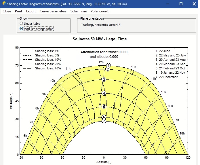
Yes, but it sais "attenuation for diffuse / albedo = 0.00000", what do you guys mean with "attenuation"? Diffuse or albedo are not considered isotropic? BR -
Tracking mode electrical losses. Bactracking algorithm
tecnun replied to tecnun's topic in Simulations
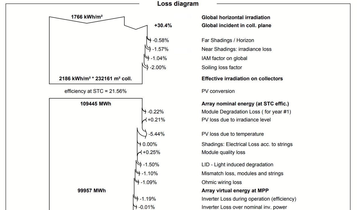
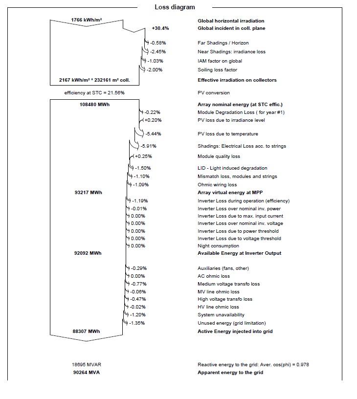
Sorry for the insistance, this issue is quite important for us for sharing it with our Clients and Technological Colleagues, in order to be comfortable with the results. Given that backtracking algorithm is set to avoid every shadow, we cannot understand why in the report, there is a percentage of shadowing identified. Let me explain with this example: As we can see it exists 1,57% of irradiance losses due to near shadings. But...let see now these table & graphs: It seems like backtracking has cancelled any shadow during the entire year of simulation. Where are these 1,57% irradiance losses imputed? Gain? it should not i think, as gain is already attributed hereinabove (30,4%). Also when we simulte shading animations in the shading scene, no shadow is spotted. Is there any explanation? Only reason i see is that 1,57% is the gaining loss due to backtracking movement, and 30,4% is "plain" gain without considering any backtracking. Is it that? BR
-
Tracking mode electrical losses. Bactracking algorithm
tecnun replied to tecnun's topic in Simulations
By the way...I'm seeing your backtracking algorithm is set to "zero shadowing". So, in the morning, trackers do not follow astronomic perpendicularity to the ray until the is NO shadow at all on the modules captation area, and in the evening trackers begin backtracking when certain shadow is spotted. This algorithm is the optimal when modules are portrait. But if not...wouldn't be a turning point different to this NO shadow which could harvests more yield (maximizes it)? And if so...are you guys intending to perform this optimization in future versions? Thanks BR Jose -
Tracking mode electrical losses. Bactracking algorithm
tecnun replied to tecnun's topic in Simulations
Thanks Dtarin for your unvalued help, now we are ok, results look quite coherent Congrats for your software improvements BR Jose -
Tracking mode electrical losses. Bactracking algorithm
tecnun replied to tecnun's topic in Simulations
Dtarin, it was at 4,9 m (default) but unticked, maybe thats the reason (i guess i m sure ?), i thought you did not have to. Tomorrow i will simulate ticking it, and with 2 separated sims to see the differences of the latter. Thanks for your agile and accurate help Best. -
Tracking mode electrical losses. Bactracking algorithm
tecnun replied to tecnun's topic in Simulations
Thanks a lot Dtarin, It was 4,9 m pitch backtracking managed. If it was 5,5 the losses would be higher as you said. Anyway i will have to combine 2 partial simulations (like it was 2 independant PV farms) and see how it behaves, let me show you the results when i got round to. Thanks again for your help :) very useful! -
Tracking mode electrical losses. Bactracking algorithm
tecnun replied to tecnun's topic in Simulations
Yes of course (and according to strings in order to enable the lack of effect of bypass diodes as it is portrait config) When we also disable the half-cell effect, the electrical losses are even higher. We have also considered an equivalent configuration but in 3H and the losses fade away even with 4,9 m of pitch BR Jose
-
Tracking mode electrical losses. Bactracking algorithm
tecnun replied to tecnun's topic in Simulations
Thanks for your response Dtarin, There are 2 issues: One theorethical (PVsyst) and the other practical (actual 50 MW PV farm data) The one i would like to double check is the theorethical point of view. The plant we are simulating through PVsyst algorithms has a 5,5 m pitch in 1/3th of the plant, and a 4,9 m pitch in 2/3th. I am attaching the report, in which we can observe a severe shadowing electrical drop (5,91%), affecting the global PR. So we have created an imaginary configuration of the plant: The whole plot with 5,5 m of pitch. And the results are absolutely greater as no electrical shadowing effects are displayed (they fade away). It is attached here as well. We acknowledge the problematic of partial shadowing in 1P (portrait) configurations, but we would like to double check this PVsyst penalization is accurate. It seems like backtracking algorithms is enabling partial shadowings and we would like to understand if they are optimized. For instance, is PVsyst software capable of deciding whether it is better (1) to lose proper angle of sun captation, or (2) to let certain partial shadowing, and if landscape of portrait configurations are taken into the equation in these backtracking internal PVsyst algorithms. Hope I could now let me explain deeper my question All comments are very welcome BR Tecnun
-
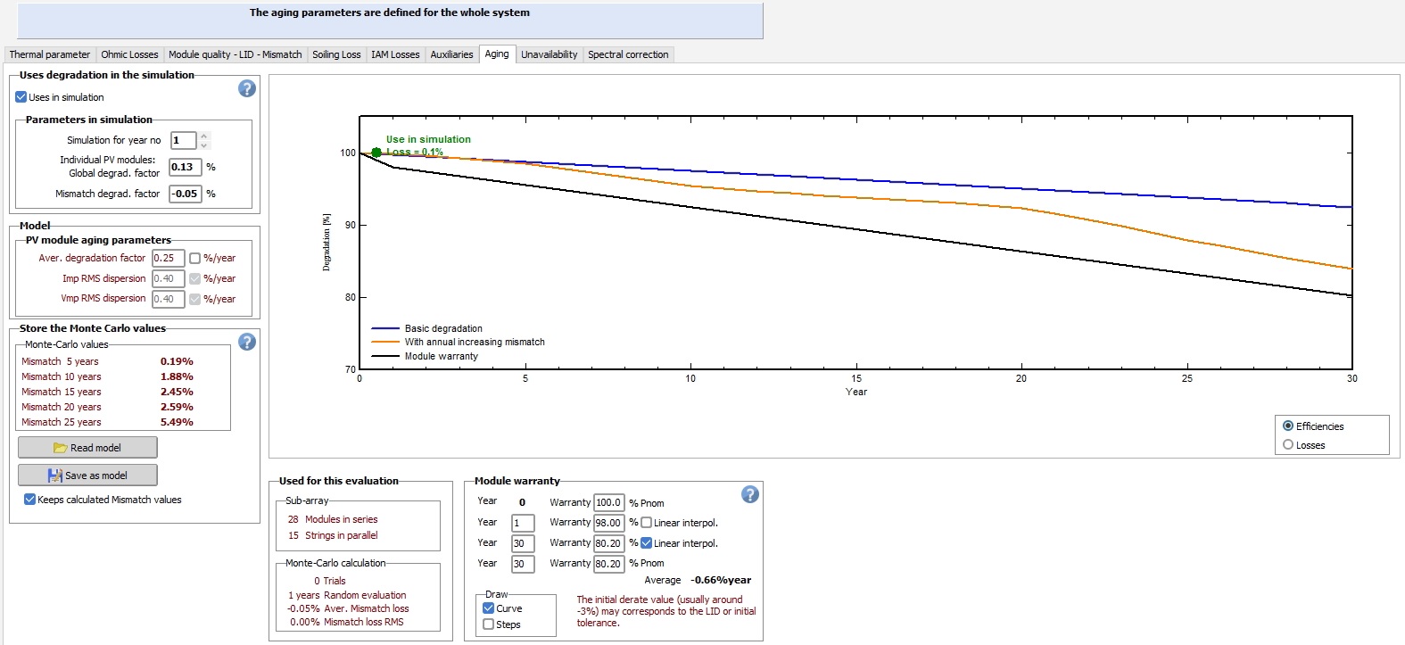
Hello, We are applying MC method for calculating module degradation along the years at non-uniform aging (certain mismatch) and we are seeing a curious shape of the curve with 2 slope turning points (2 "humps") as i m attaching. Does it answer to any physical cause? ... Should not be more homogeneous as in the middle of the period it does not exist any appreciative event? BR Jose
-
Hello, We've been encountering some severe electrical losses in several 1V tracking mode Utility Scale PV farms, where pitch is a little tight (less than 5 m). For instance, at 5,5 m no electrical shading losses are founded, but at 4,9 m we found a huge drop in PR due to >5% electrical shadings. Does it make sense? Could it be due to an incorrect backtracking algorithm? What we would expect is an angle shorten during the morning and during the evening like the simple drawing we are attaching. If we simulate it in 2H instead of 1V there is no such electrical shadings, we attribute it to the bypass diode effect, what we find it cool, but in tracking mode we should not expect it. If the backtracking applies there will be a gaining drop but no so accused as it is reflected now with such a severe electrical drop. Is there some explanation to this effect? Best. Jose
-
Hello, Is it possible in PVsyst to simulate with measured global irradiance on plane particulary in tracking scenes? In custom METEO conditions it is possible for fixed structures but I am not sure whether it is feasible for trackers. Thanks BR
-
Are you answering this topic? Please need clear answers, maybe not as detailed as my questions but at least reasonably clear. "If you are unable of explaining smth with simplicity it means you dont fully understand it" Albert Einstein


accordingtostrings_1.jpg.86e525b73b3d5427b4bb420ab90e11e8.jpg)
accordingtostrings_2.jpg.cc196e1e6a2eb3ab5c2326fb1cdb0a0a.jpg)
systemlosses.jpg.4c737f3c75f841b98b43d75e356acb43.jpg)